By the SeeZol field engineering team · September 2026 · 8 min read
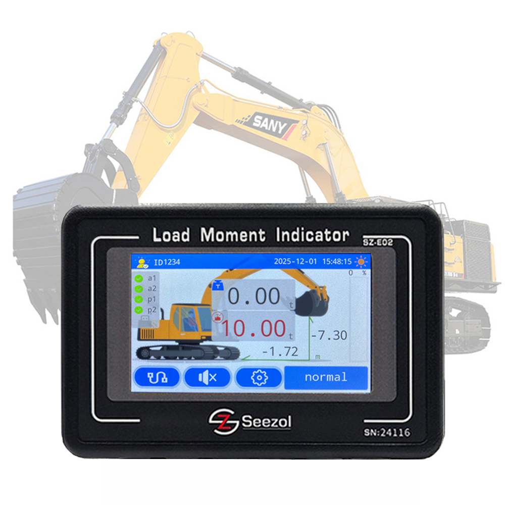
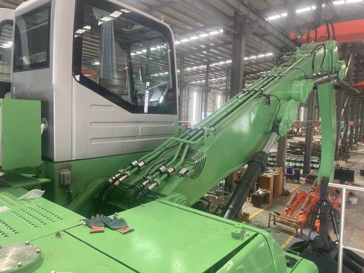
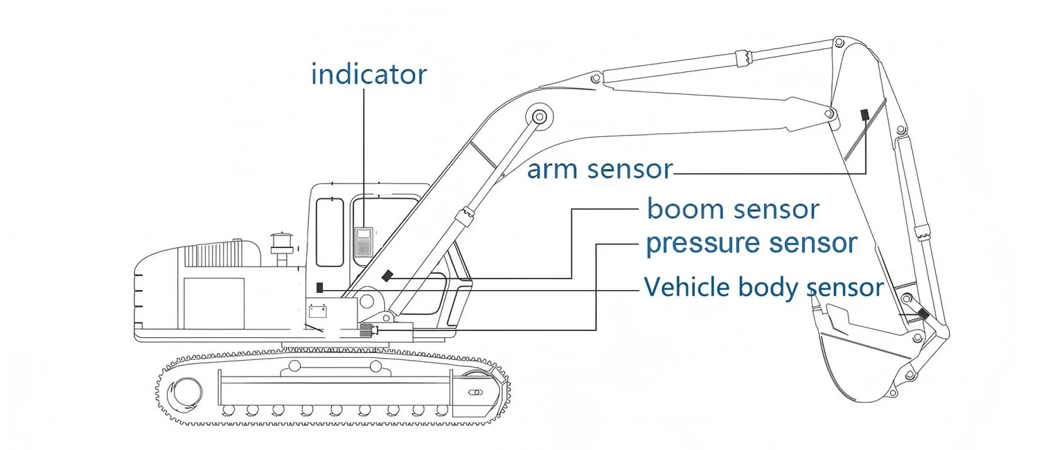
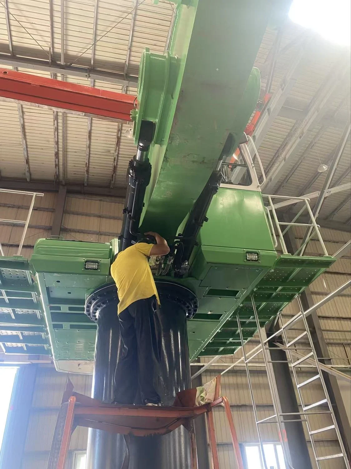
In September 2026, on the assembly floor of Shandong Pengcheng Max Engineering Machinery in Rushan, Weihai, we fitted a SeeZol SZ-EM02 material handler load moment indicator to a 50-tonne hydraulic grab machine.. The sensing chain runs five sensors in total: two pressure sensors landed on the lift cylinder’s supply and return lines, and three angle sensors watching the body, the boom and the stick. This field report records the whole arc — site survey, position selection, mounting, calibration — and shows how the safety package an export machine has to carry gets installed, calibrated and turned into a repeatable template at the assembly stage.
1. The customer and the machine
Shandong Pengcheng Max Engineering Machinery Co., Ltd. is not a trading office with a showroom. It builds complete machines. The company moved into Rushan, on the Weihai coast, in 2023, and in 2024 broke ground on a 349-mu manufacturing base — a ¥1.4 billion investment covering 147,000 m² of floor area and four production workshops. It is the first complete-machine engineering machinery base in Weihai. Three of the four workshops are already in production. More than 90% of what leaves the line is exported.
That export ratio is what decided the nature of this retrofit. A machine delivered to an overseas buyer has to travel with a safety package the buyer can actually check: a calibration certificate, the rated capacity chart the controller is actually running, and manuals in the operator’s language. None of those can be added by after-sales. They are installed and documented at the assembly stage, or not at all.
The unit on the line that week was a 50-tonne-class hydraulic material handler — long boom, grab attachment, the frame that works scrap yards, steel mills and bulk terminals. Its normal state is continuous duty, not the occasional lift.
2. Why a grab machine is a harder LMI problem than a crane
A truck crane is a solved problem. Its rated capacity chart is a lookup table: boom length × radius → maximum load. The operator reads the chart, picks a configuration, and the rest is execution.
A material handler differs in three ways:
- It works in cycles, not lifts. Grab, swing, release, repeat. The safety device has to be awake for every cycle, not just for the moment a lift starts.
- Rated load changes continuously with radius. The operator deliberately sweeps the grab across the whole radius range, so the system spends far more of its life near the limits than a crane ever does.
- Nobody writes a lift plan for a grab. A crane lift has a method statement and a banksman. A grab machine has one operator making the call in real time.
Regulators treat overload protection as mandatory equipment rather than an option. The ISO 10245 series (cranes — load limiting and indicating devices), China’s GB/T 12602, and EN 13000 for mobile cranes all describe the same thing: what a material handler load moment indicator must detect,, and how it must respond. For a machine heading overseas, that paperwork travels with the machine.
3. What we fitted: the SZ-EM02 material handler load moment indicator
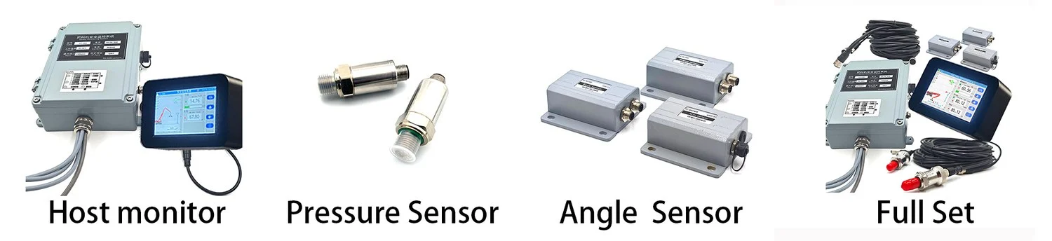
System model SZ-EM02, SeeZol’s hydraulic material handler load indicator. The same sensing chain also ships as a material handler weighing system: the hardware that protects the machine is the hardware that bills the load. That overlap is deliberate, and it shapes how we specify the product line.
| Working voltage | DC 12–36 V |
|---|---|
| Working / storage temperature | −20 °C to +70 °C |
| System error | ±3% |
| Display error | ±3% |
| Relay contact capacity | AC 220 V / 3 A |
| Protection level | IP65 |
| Displayed values | Load weight, working radius, height |
| Logging | Overload records, real-time grab-cycle weighing, per-customer and per-shift weight logs |
The sensor figures are listed together, because they set the ceiling for the whole chain:
| Component | Model | Key figures / mounting |
|---|---|---|
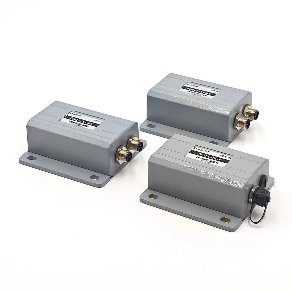
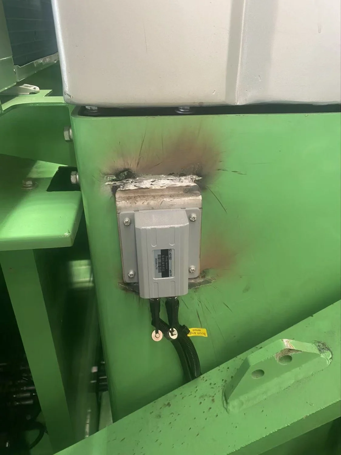
| Angle sensor (body) | SZ-A01BD | Range ±10° to ±90°, resolution 0.05°, absolute accuracy 0.1°, response 0.02 s, 9–36 V DC, IP67; welded to upper structure |
| Angle sensor (boom) | SZ-A01BM | Same measuring platform; current, voltage, RS232 or RS485 output; welded to boom side |
| Angle sensor (stick) | SZ-A01AM | Same measuring platform; current, voltage, RS232 or RS485 output; welded to stick side |
| Hydraulic pressure sensor ×2 (supply line P1 / return line P2) | SZ-P201S (0–400 bar) | 4–20 mA output, 0.5% F.S. accuracy, absolute accuracy 0.1 bar, 12–30 V DC, response 0.02 s, IP67; teed into lift cylinder test ports |
| Data acquisition & control unit | Safety monitoring host | CANopen bus, pressure channels P1/P2, three angle inputs, relay outputs K1–K3, RS485, USB logging |
One number deserves explaining, because quotation sheets often blur it. The pressure sensor’s 0.5% F.S. looks far better than the ±3% system figure — and it is. The sensor is not the weak link. The ±3% is what survives the whole chain: pressure, geometry, algorithm, display. On a 50-tonne machine that is ±1.5 t.
4. How a material handler load moment indicator is installed, sensor by sensor
4.1 Body attitude sensor — a weld-on bracket on the upper structure
4.2 Boom and stick angle sensors — three angle sensors, three segments
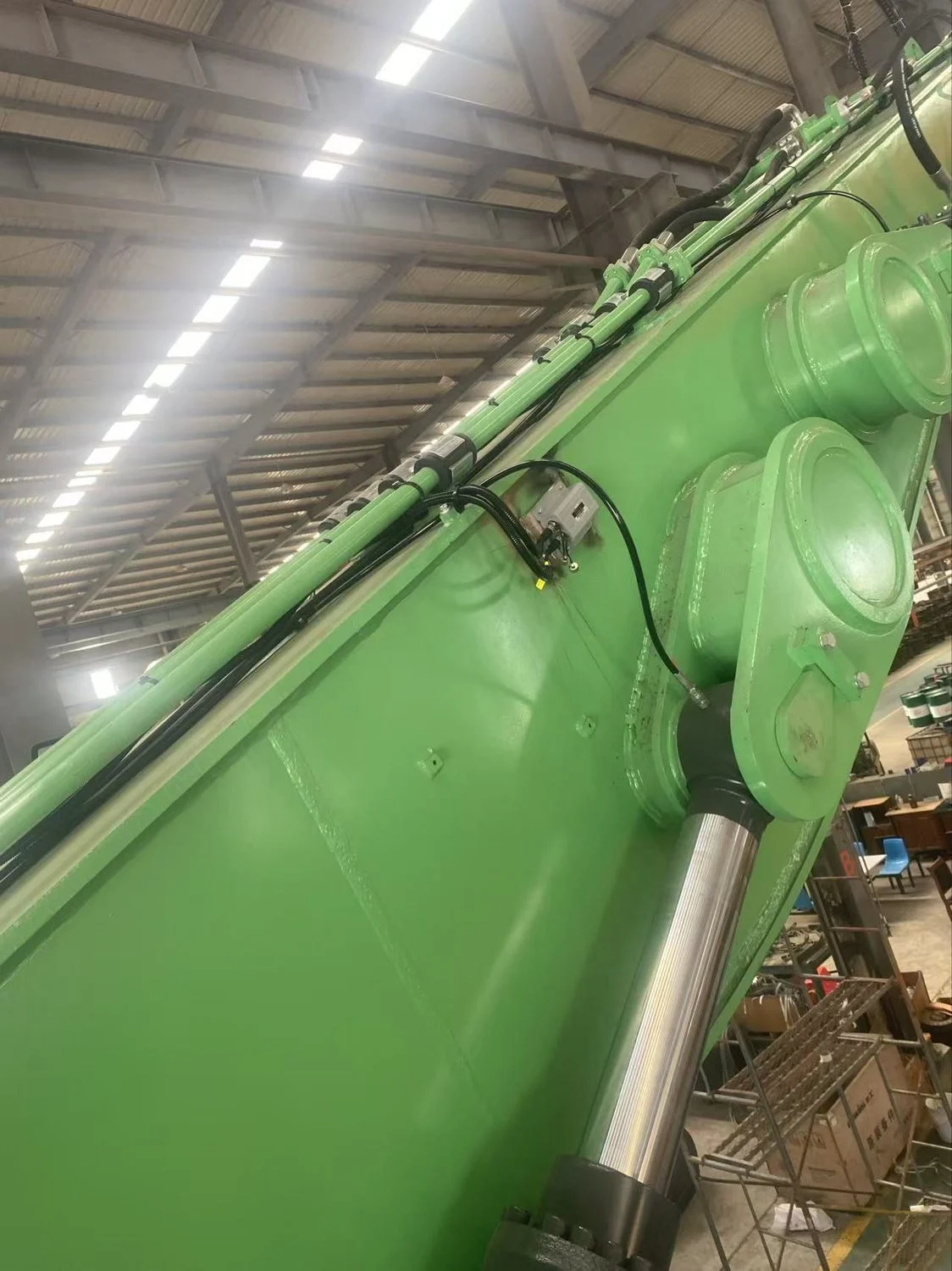
The boom sensor SZ-A01BM reports luffing angle. Material handler booms are long and the geometry near the extreme radii is non-linear — which is exactly why calibration points cannot be skipped.
The stick sensor SZ-A01AM reports stick articulation. The grab is mounted at the end of the stick, so the stick angle sets the grab’s horizontal distance from the machine — its effective radius. Body, boom and stick angles together are what let the controller know where the grab actually is in space. All three come off the same SZ-A01 measuring platform; only the mounting position differs.
4.3 Pressure sensors ×2 — one on supply, one on return
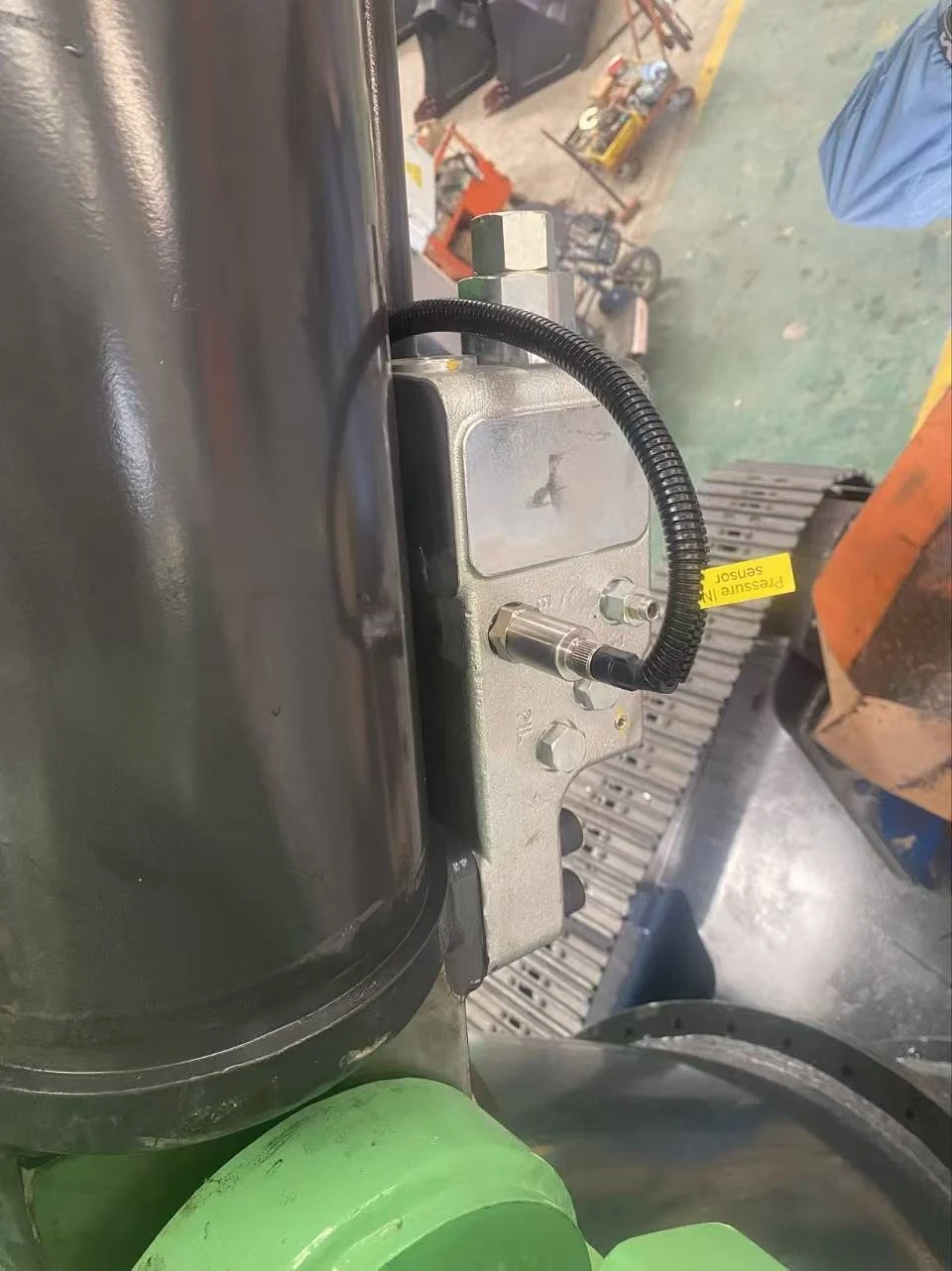
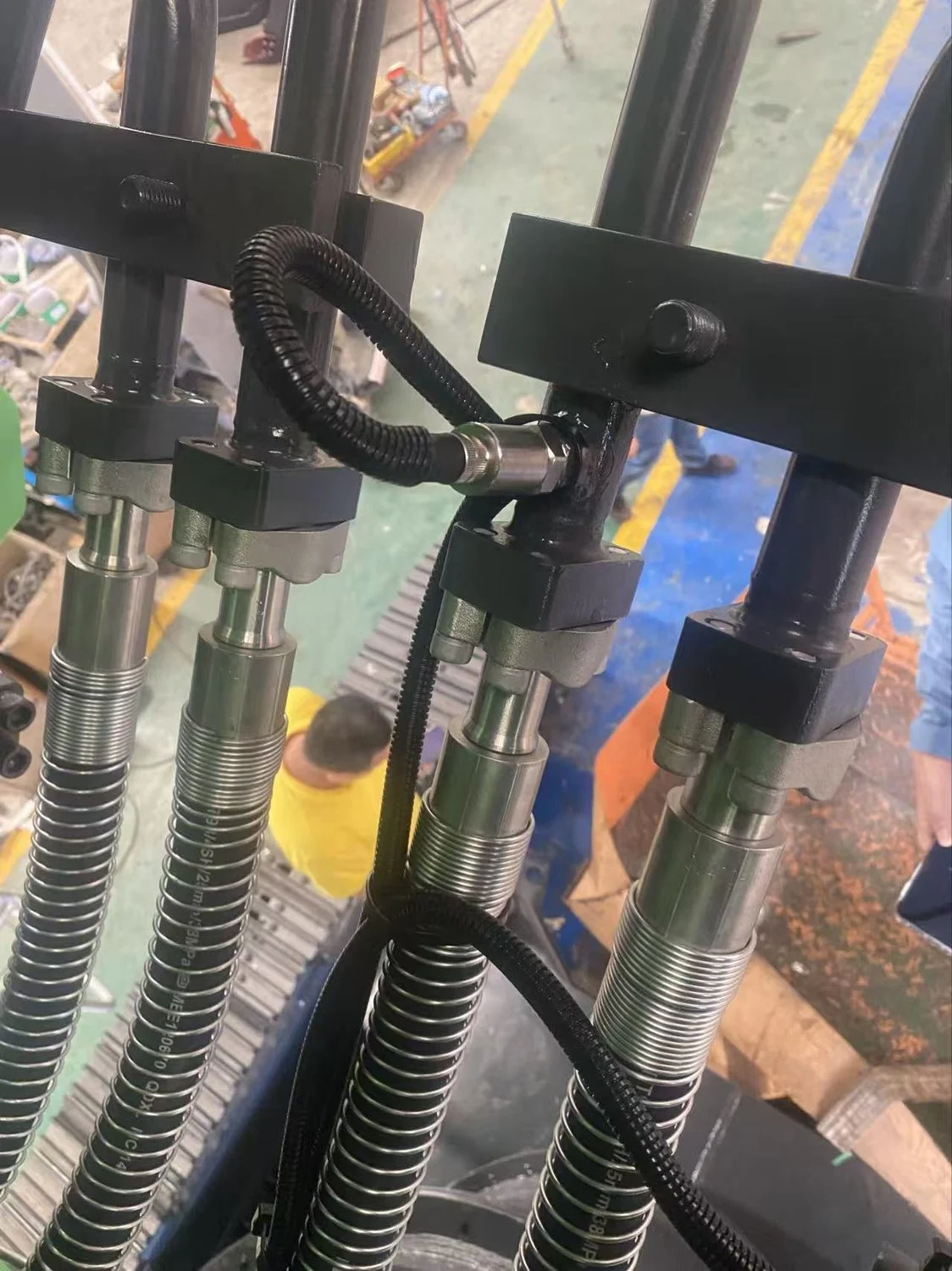
This 50-tonne machine runs two SZ-P201S pressure sensors: one teed into the lift cylinder’s supply line — the primary signal for lift force, mapped to host channel P1 — and one into the return line (P2) for cross-check and redundancy. Sampling both is what gives the controller’s estimate its safety margin. Both follow the rule below. SeeZol pressure sensors ship with a standardised ¼-inch interface, which reduces the field work to bridging the sensor’s ¼ end to the machine’s hydraulic end. How that bridge is built depends on how the machine’s pipework is joined, and there are three documented methods: a tee at an existing threaded joint, a flange at a clamp or quick-coupler joint, or screwing straight into the main test port on the machine’s burst (balance) valve. Which one applies is decided by the machine, not by the catalogue.
4.4 Cable routing — corrugated conduit, tied to the machine’s own lines
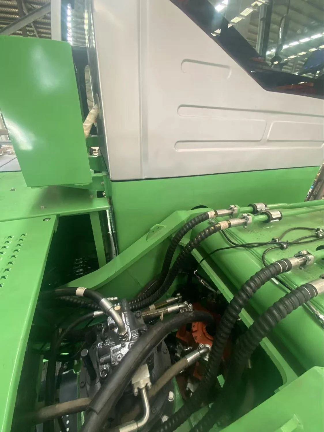
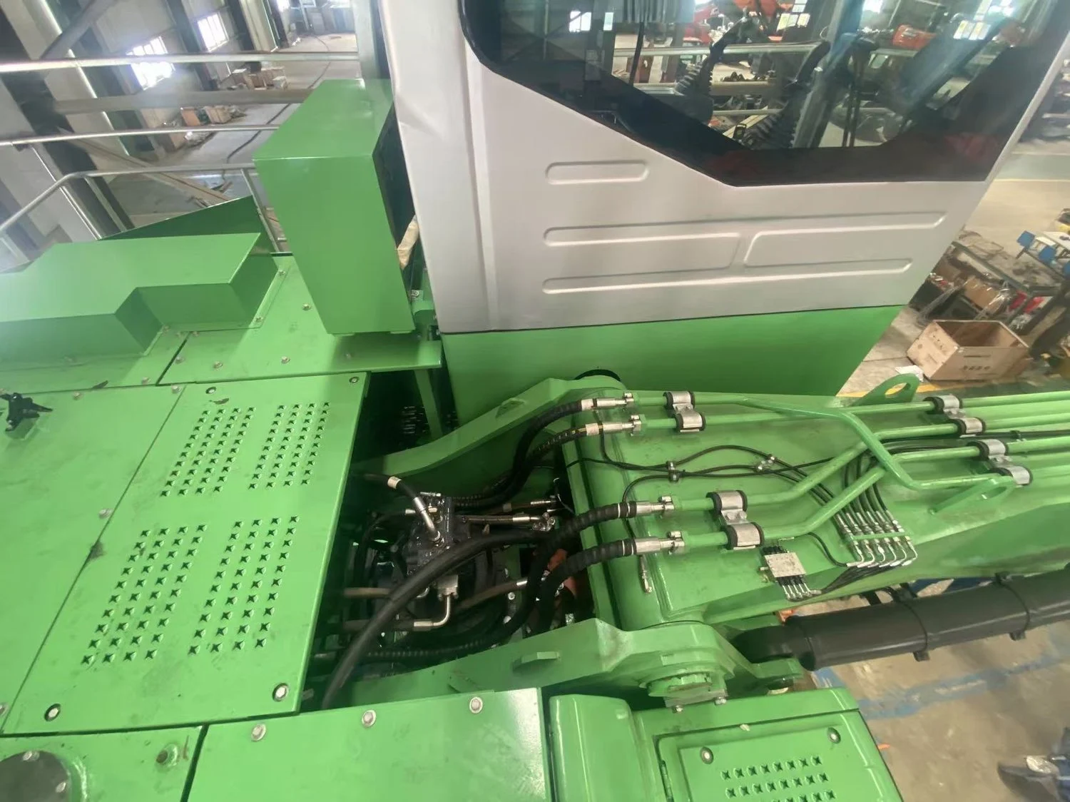
Three rules govern the routing: corrugated conduit over the whole length; run along the machine’s existing hydraulic channels and fixings, which keeps it neat and mechanically secure; and leave appropriate slack where boom movement stretches the hoses, so the signal cable is never pulled tight or snapped.
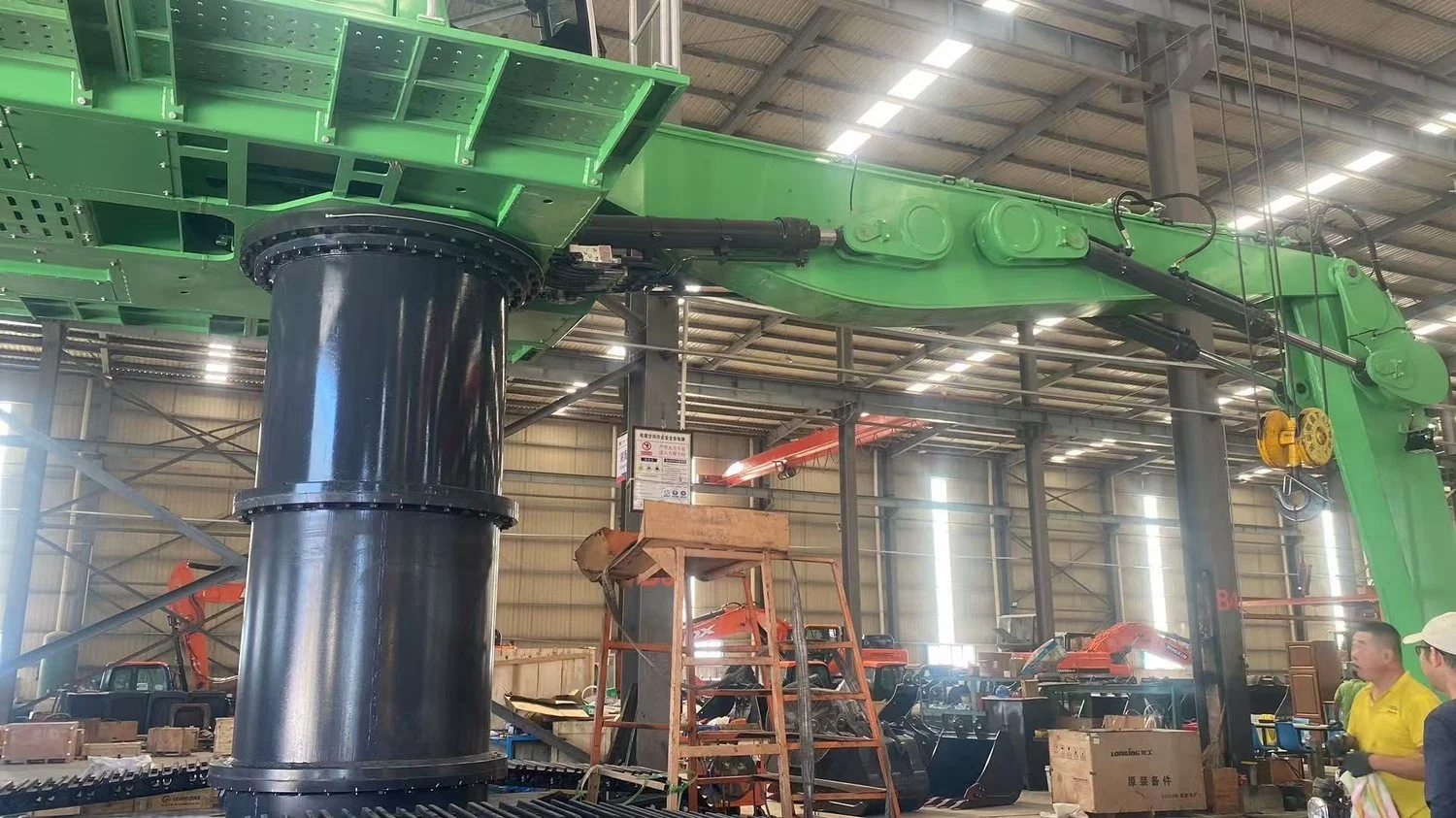
5. Commissioning
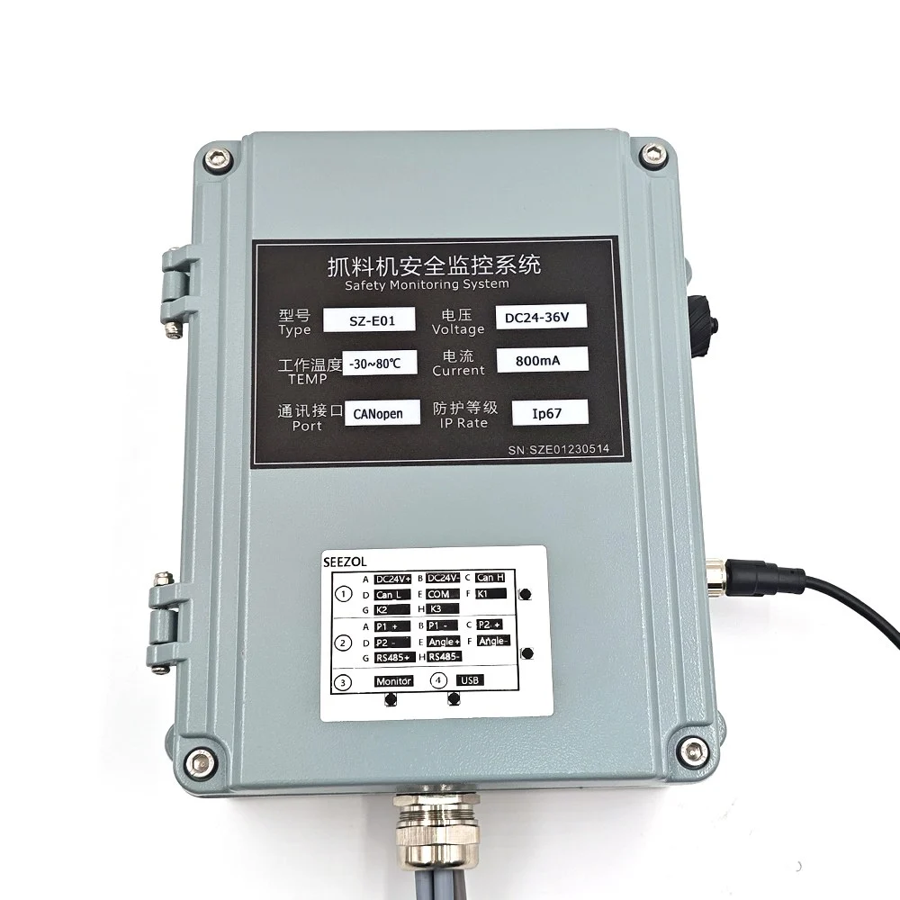
Wiring the machine is the first step. Calibration is what gives a material handler load moment indicator its judgement.
- Zero first. With the machine level and at rest, the controller establishes its reference.
- Then load in steps. Known test loads across several boom radii. Three points is our floor; on grab duty the geometry is non-linear at the extremes, so we would rather see five.
- Finally, verify the outputs. K1 and K2 carry the warning; K3 cuts the dangerous motion if the operator keeps going. Pre-warning and mid-event blocking are one capability with two halves — half of it is no protection at all.
On accuracy, stated completely: this machine runs at ±3% system error. Its job is overload warning and limiting, not trade-level metering. If grab weights are going onto an invoice, the accuracy budget and the calibration interval both change. Those are two different acceptance criteria, and which one you need should be settled at selection stage, not after delivery.
6. Field notes: three things that decide whether the system is still switched on next year
- Measure the thread before choosing anything. Getting a pressure take-off dimension wrong is the most expensive mistake on the chain, because it takes sealing and accuracy down together. See 4.3.
- Slack at the pivot. Raising the boom stretches the hydraulic run. If the signal cable is stretched with it, the signal cable is what breaks. This is the step most often skipped on site.
- Orientation against the swept volume. Mount on the inner side where possible to reduce exposure to impact, then walk every boom posture and confirm that neither machine nor obstacle can scrape the sensor or cable.
- Calibration is a schedule, not an event. Re-check zero after boom repair, hydraulic work or long-distance transport, and add a mid-year check on multi-shift duty. Lose the operator’s trust and the system becomes a lit-up screen — which is the same as not having one.
7. What the customer gets
- Warning before, cut-off during. Not a device that beeps, but one that can stop the dangerous movement.
- Weight data per grab cycle. Every grab is logged, so invoiced tonnage matches loaded tonnage; per-customer and per-shift logs export from the controller.
- Documents that travel with an export machine. Calibration certificate, the rated capacity chart the controller is running, and manuals in the operator’s language — all of which have to be complete at handover.
- A repeatable package. Sensor positions, bracket drawings and cable lengths carry over to unit two and unit three, so the first machine’s workload is not repeated on every one.
8. What this means for Pengcheng Max
Exporting more than 90% of output means every machine delivered carries the same safety package. The value of the first unit is not that it was fitted — it is that sensor positions, bracket drawings, cable routing and calibration records become a template. After that it is a production management problem, not an engineering one.
It is the same path our previous project on this machine class took: the 300-ton port transfer material handler at Huanghai Machinery. That machine was a different order of scale entirely — boom pivot close to 10 m above ground, sensor points above 10 m — but the sequence was identical: site survey, structural evaluation, position selection, installation, stepped calibration, acceptance. Once the LMI is in, the next step is usually the weighing system and the data platform: from single-point safety protection to whole-machine digital management.
9. Questions we get asked on site
Can a 50-tonne machine be calibrated indoors, at the factory?
Yes. Calibration needs known test loads applied in steps across several radii. This machine was calibrated at the assembly stage, and the calibration record ships with the machine’s documentation. Machines already in service need a window carved out of production instead.
Is a material handler LMI the same as a load limiter?
Not quite. An LMI continuously displays the measured moment against the rated capacity chart; a load limiter focuses on intercepting dangerous movement at a set threshold. SeeZol’s current controller combines both — this comparison covers the difference in detail.
How many sensors does one machine need?
It depends on the structure. This 50-tonne machine runs a complete set: three angle sensors — body SZ-A01BD, boom SZ-A01BM and stick SZ-A01AM — plus two SZ-P201S pressure sensors, one on the lift cylinder’s supply line (channel P1) and one on the return line (P2), five in total. Whether another model gains or loses a sensor comes down to boom sections and whether the hydraulic circuit has dual test ports — set by structure, not by tonnage class.
Which part fails first?
Sensors fail before controllers do. So a fair question before signing is the lead time and price of a spare angle sensor and pressure sensor. If the answer is “we’ll check”, check the next supplier.
Does it work in cold or high-humidity environments?
Working temperature is −20 °C to +70 °C, with an IP65 warning and display unit and IP67 sensor bodies. Rushan is a coastal base, so humidity and salt spray are the normal condition — check protection ratings against that environment, not against an inland workshop.
Send us your machine details and get a configuration proposal within one business day.
What we need: machine model, rated capacity or grab weight, typical working radius, and the working environment (scrap yard, steel mill, terminal, cold store, coastal). We will come back with the sensing chain, mounting positions and a calibration plan — not just a model number. Contact us →