Mention légale : SeeZol fabrique des indicateurs de moment de charge, des limiteurs de capacité nominale et des systèmes de pesage embarqués destinés aux grues et aux équipements de levage. Cet article a été rédigé par notre propre équipe éditoriale, et les produits mentionnés dans la section finale sont les nôtres. Tous les faits relatifs à l'incident sont tirés de rapports publics et du texte officiel des normes citées ; l'analyse technique et les opinions exprimées sont celles de la rédaction et ne représentent en aucun cas celles d'une autorité de régulation ou d'une partie impliquée dans cet incident.
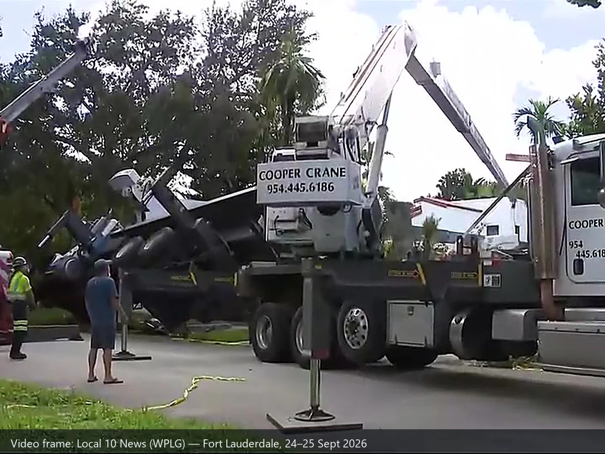
Introduction : Le jeudi matin 24 septembre 2026, un camion-grue s'est renversé sur une maison dans le quartier de Rio Vista, à Fort Lauderdale, en Floride. Il avait été loué pour hisser une tente de fumigation anti-termites sur le toit. Quelques heures plus tard, la grue venue la retirer du toit s'est effondrée à son tour. Personne n’a été blessé — la maison venait de faire l’objet d’une année de travaux de rénovation et il n’y avait personne à l’intérieur — mais deux grues se sont retrouvées sur le même toit, et ces deux défaillances font toujours l’objet d’une enquête.
Deux pannes de grue en une seule journée constituent un événement suffisamment rare pour qu'il mérite d'être examiné de près, et ce pour une raison bien précise : Les deux défaillances se situent de part et d'autre de la limite de détection d'un indicateur de moment de charge. Le deuxième cas — une flèche à cinq sections entièrement déployée, soulevant une charge dont personne n’avait déterminé le poids — s’inscrit parfaitement dans la plage de fonctionnement d’un LMI. Le premier cas — le sol cédant sous un stabilisateur chargé — se situe en dehors de cette plage, et ce sera toujours le cas.
C'est précisément cette limite qui fait l'objet de cet article. C'est aussi ce que notre secteur a le plus de mal à expliquer, car la réalité, telle qu'elle est, est moins flatteuse pour le matériel que le discours commercial.
1. Que s'est-il passé, dans l'ordre ?
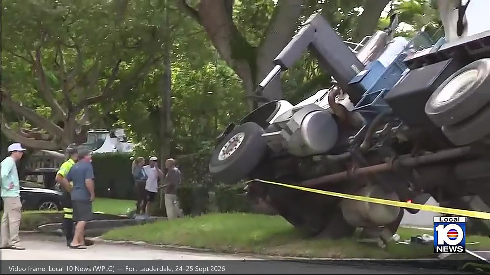
D'après des informations provenant de CBS News Miami, WPLG Local 10, NBC 6 South Florida et du site spécialisé dans le secteur de la musculation Vertikal.net :
| Article | Comme indiqué |
|---|---|
| Date / heure | Jeudi 24 septembre 2026. Les pompiers de Fort Lauderdale ont reçu le premier appel au 911 vers 9 h 15. |
| Lieu | 8e rue Sud-Est, quartier de Rio Vista, Fort Lauderdale, comté de Broward, Floride. La chaîne WPLG Local 10 rapporte que bloc des numéros 700; NBC 6, citant les pompiers de Fort Lauderdale, rapporte que le bloc 800. Les deux versions divergent, et cet article les présente toutes les deux. |
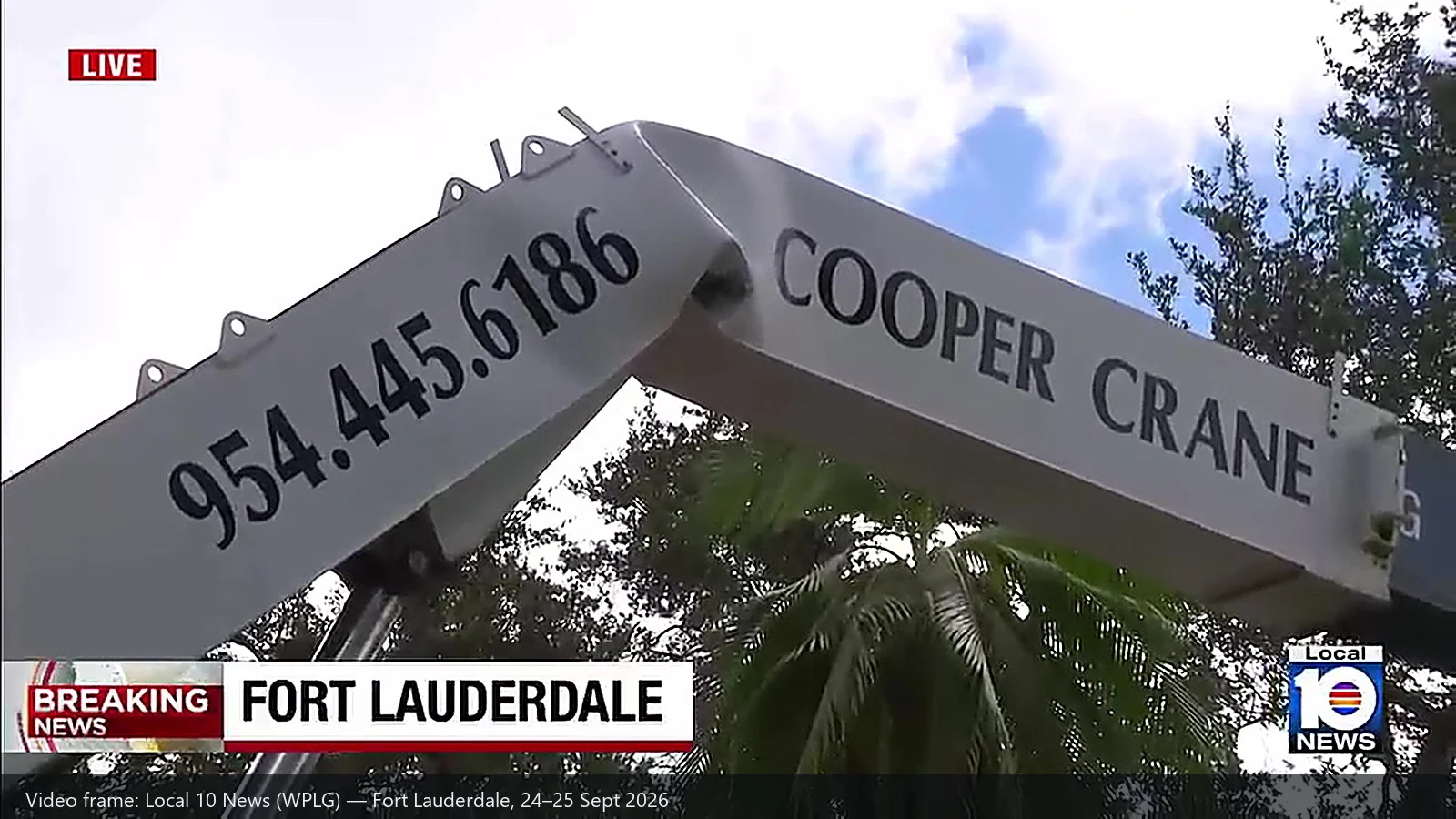
| Équipement | Un camion-grue (grue télescopique montée sur camion) appartenant à Cooper Crane, une entreprise basée à West Park, en Floride. La deuxième machine a été décrite comme un camion-grue de plus grande taille. |
| Tâche | Un prestataire spécialisé dans la lutte contre les nuisibles utilisait la grue pour installer une tente de fumigation sur le toit dans le cadre d'un traitement contre les termites — une intervention courante dans le sud de la Floride. |
| Échec n° 1 | Le vérin de stabilisation avant, côté chargement, a cédé — tombant peut-être dans un vide — et le camion s'est renversé. Selon les témoignages, les pieds de stabilisation ont été arrachés du sol. La flèche s'est abattue sur le toit et la paroi arrière. |
| Échec n° 2 | Quelques heures plus tard, alors qu’une deuxième grue, plus grande, était en train de dégager la première, la section de base de la flèche de cette grue s’est déformée. La grue de dépannage avait sa flèche à cinq sections entièrement déployée et effectuait le levage à l’aide d’un seul câble, avec une élingue fixée à mi-hauteur de la flèche de la grue tombée. |
| Blessures | Aucun. La maison était inoccupée ; les propriétaires venaient de terminer des travaux de rénovation qui avaient duré un an. |
| Réponse | Une équipe spécialisée dans les matières dangereuses est intervenue suite à une fuite de gazole ; un inspecteur des pompiers et un inspecteur municipal des bâtiments étaient présents ; le bâtiment a été déclaré dangereux ; des inspecteurs de l'OSHA se trouvaient sur place pour s'entretenir avec les travailleurs. |
| Ce qui suit | Les opérations de nettoyage se sont poursuivies jusqu'au vendredi 25 septembre : les équipes ont récupéré le liquide hydraulique déversé et ont fait venir un gros camion pour démonter et évacuer l'équipement endommagé (WPLG Local 10). Cooper Crane a fait appel à une équipe spécialisée pour démonter les flèches. L'entreprise a déclaré qu'elle coopérait avec le propriétaire du terrain, les autorités et son assureur, et qu'elle ne pouvait pas s'exprimer sur les détails tant que l'enquête était en cours. |
Le commentaire d'un voisin, repris par CBS News Miami, va droit au but : « Si l’on examine la conception des semelles, on constate qu’elles n’utilisaient pas une semelle suffisamment grande pour répartir la charge, et que celle-ci n’était pas vraiment importante. » C'est à l'enquête qu'il reviendra de déterminer si cette observation se vérifie.
2. Ce que mesure réellement un indicateur de moment de charge
Avant de pouvoir situer ces deux défaillances de part et d'autre de la ligne, il convient de préciser certaines choses concernant l'instrument lui-même. Un indicateur de moment de charge ne « détecte » pas une « surcharge » dans l'abstrait. Il effectue un calcul, en continu, à partir des données mesurées.
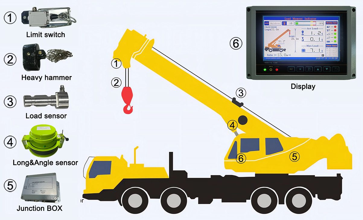
Charge × rayon = moment de charge. Le système compare ce moment calculé à la valeur nominale correspondant à la configuration qui lui a été indiquée, et intervient lorsque les deux valeurs se rapprochent. Tout le reste d'un LMI s'articule autour de ces trois étapes : mesurer, calculer, comparer — puis avertir ou arrêter.
| Ce qui est mesuré | Avec quoi ? | Ce que cela devient |
|---|---|---|
| Force exercée sur le câble de levage / au niveau du bloc de crochet | Capteur de charge (cellule de charge) dans le câble de roulement ou à l'extrémité fixe | Charge réelle — affichée directement en tonnes ou en livres |
| Pression dans le circuit hydraulique de levage ou de basculement | Transducteur de pression hydraulique | Une méthode indirecte pour déterminer la charge réelle, lorsqu'aucun capteur de force n'est installé |
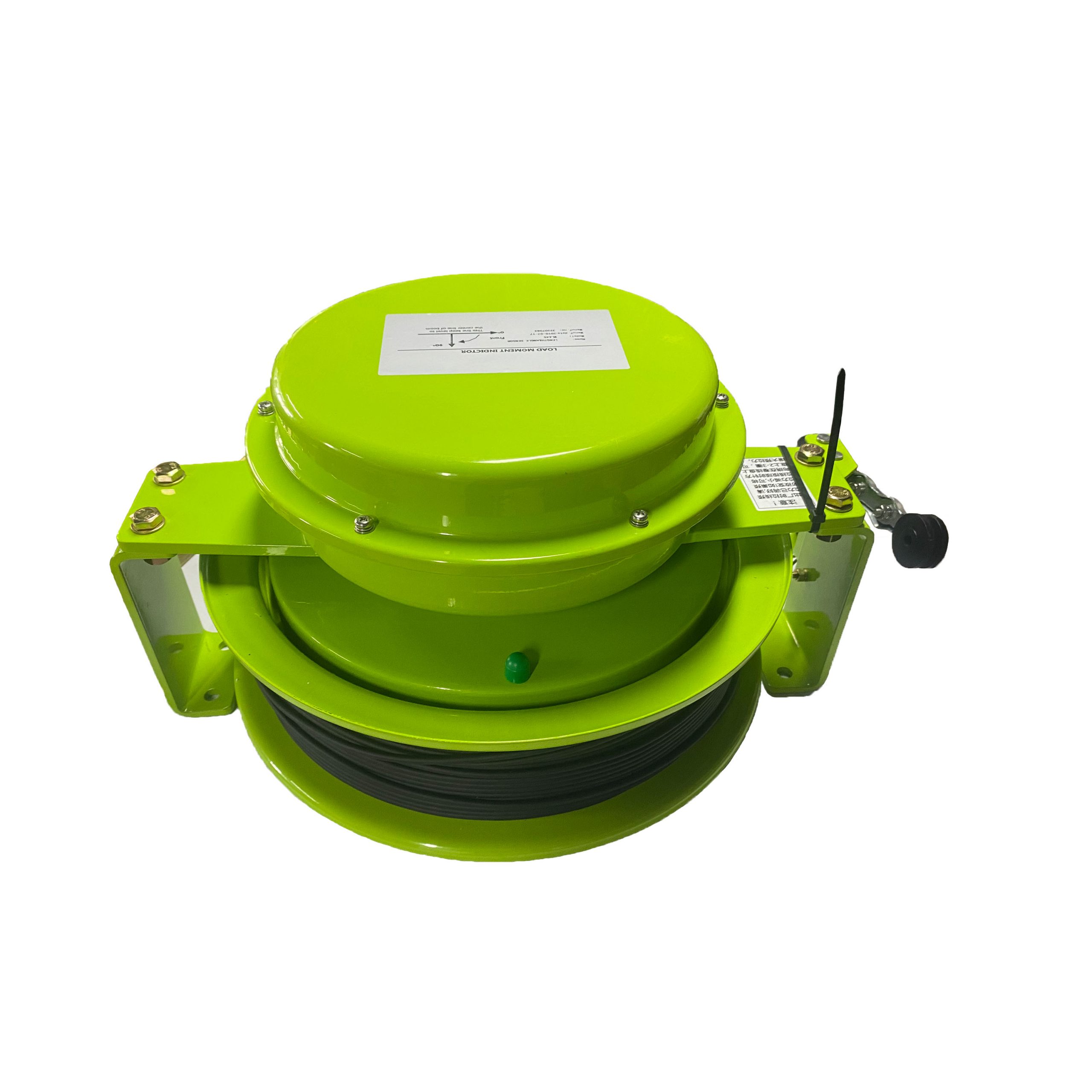
| Longueur de la rampe | Capteur de longueur sur l'enrouleur de câble ou codeur à câble sur la flèche | Rayon et angle |
| Angle de bôme | Capteur d'angle situé à la base de la flèche ou sur un pendule | Rayon et hauteur de la tête |
| Moment de charge calculé | D'après ce qui précède | Pourcentage de la puissance nominale — valeur à partir de laquelle l'alarme et le disjoncteur se déclenchent |
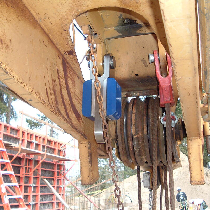
Concrètement, cette architecture offre un ensemble spécifique de fonctions — et il est utile de les énumérer clairement, car elles définissent les limites :
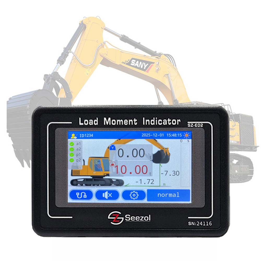
- Affichage en temps réel de la charge réelle, du rayon, de la longueur de la flèche, de l'angle et du pourcentage de la capacité nominale. Ce n'est pas un voyant d'alerte, mais un chiffre que l'opérateur peut surveiller de près.
- Système d'alerte et de coupure en deux étapes. Une plage d'alerte précoce et une limite à partir de laquelle le système prend le relais — généralement en interrompant les mouvements qui augmentent le moment : levage, extension télescopique, abaissement de la voile.
- Gestion de la configuration. Les valeurs nominales dépendent de la configuration indiquée au système : combinaison de flèche, flèche auxiliaire ou flèche volante, contrepoids, et extension totale ou partielle des stabilisateurs. Les courbes de performance d'une machine sur stabilisateurs et de la même machine sur pneus sont différentes.
- Enregistrement des événements et, sur les systèmes plus récents, télématique. Cycles de charge, valeurs de crête et événements d'alarme ou de contournement : enregistrés plutôt que perdus. C'est cette fonctionnalité qui transforme une machine en source de données après un incident, au lieu d'une machine qu'il faudrait reconstituer à partir des vidéos prises par des témoins.
Chacune de ces fonctions repose sur quatre hypothèses, et ce sont elles qui déterminent où se situe la limite : que la machine soit à niveau, que les stabilisateurs supportent la charge prévue, que la configuration saisie corresponde à celle utilisée, et que le système n'ait pas été contourné.
3. Deuxième défaillance : la défaillance pour laquelle un indicateur de moment de charge a été conçu
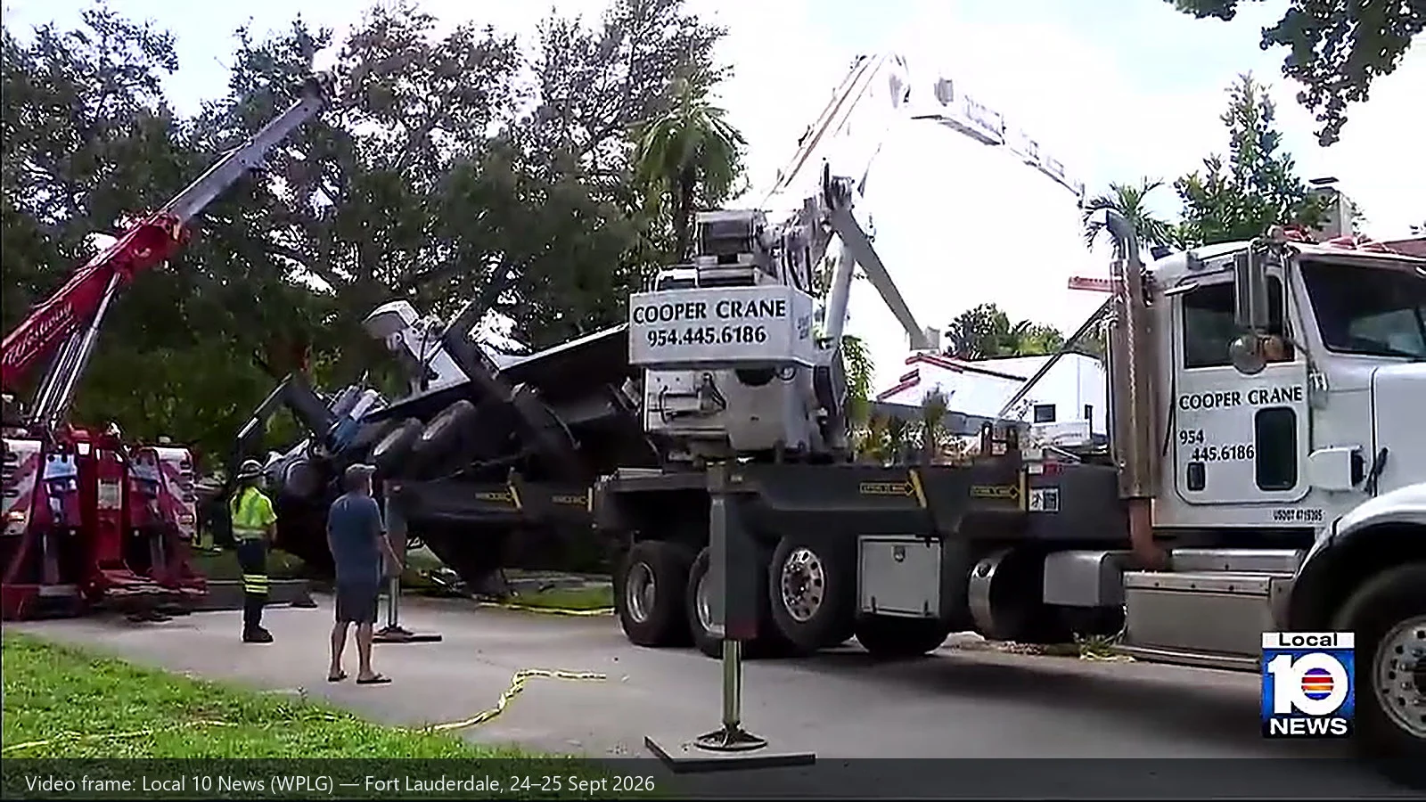
Une grue renversée semble être une grandeur connue. Sa masse est documentée, et son propriétaire sait exactement de quel modèle il s’agit. C’est là que réside le piège. Le chiffre qui importe pour la grue de dépannage n’est pas le poids brut de la machine tombée, mais la force nécessaire pour la dégager et la maintenir en place. Cette force résulte de facteurs que personne ne peut déduire d’une plaque signalétique : l’aspiration et l’enfoncement dans le sol, l’interférence structurelle du bâtiment contre lequel elle s’appuie, la géométrie des élingues, et le fait qu’un dégagement puisse être suffisamment brusque pour transformer une charge statique en charge dynamique.
Face à ces quatre inconnues, un LMI n'offre qu'une seule chose — et dans ce scénario, c'est justement ce qui compte. Il peut peser la charge alors qu'elle ne quitte que très légèrement le sol.
La réglementation américaine ne se contente pas d'autoriser cette méthode ; elle en fait l'une des deux voies légales. L'article §1926.1417(o)(3) impose à l'opérateur de vérifier que la charge ne dépasse pas la capacité nominale, soit en déterminant son poids à partir d'une source reconnue par le secteur, soit à l'aide d'une méthode de calcul, avant le levage, ou en commençant le levage et en utilisant un dispositif de pesage de la charge, indicateur de moment de charge, un indicateur de capacité nominale ou un limiteur de capacité nominale permettant de déterminer si la charge dépasse 75 % de la capacité nominale maximale au rayon le plus long qui sera utilisé. Si tel est le cas, l'ascenseur doit s'arrêter jusqu'à ce que la charge ait été correctement stabilisée.
— OSHA 29 CFR 1926.1417(k)
Si l'on lit ces deux dispositions conjointement, les consignes d'utilisation d'un treuil de sauvetage s'imposent d'elles-mêmes. L'appareil indique la charge supportée par un crochet de trois pouces ; la réglementation précise le seuil à partir duquel il faut interrompre l'opération. Il manque toutefois trois éléments à cette configuration, que nul appareil ne fournit : un LMI configuré pour la flèche et le gréement effectivement utilisés (cinq sections déployées, une seule ligne, une élingue au milieu de la flèche : ce n'est pas la configuration présentée lors de la démonstration de la semaine dernière), une personne habilitée à interrompre l'opération à ce moment-là, et un appareil capable de fournir une mesure fiable dès le départ — la différence est mise en évidence dans notre comparaison de pesage embarqué vs indicateur de charge vs balance de charge.
4. Première défaillance : l'indicateur de couple à vide à mi-course est en surveillance
Passons maintenant de l'autre côté de la ligne. Un indicateur de moment de charge est placé au-dessus du vérin de stabilisateur. Cette simple phrase explique parfaitement la première défaillance.
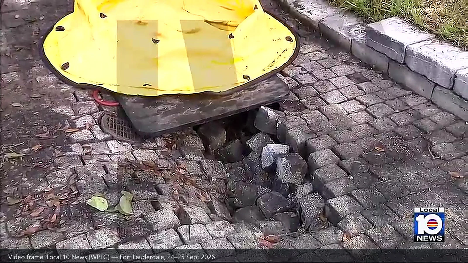
Un tableau de charges n'est pas une caractéristique propre à la grue seule. Chaque capacité nominale qui y est indiquée repose sur trois hypothèses : que la machine soit à niveau, que les stabilisateurs soient entièrement déployés conformément aux spécifications, et que le sol sous chaque flotteur ou patin puisse supporter la réaction qu'il subit. Seules les deux premières conditions sont contrôlées par des instruments. Si un patin s'enfonce de trois pouces dans un remblai qui n'a jamais été compacté, les instruments de la grue indiqueront une capacité de levage tout à fait normale alors que la grue est déjà en train de basculer. La chaîne de mesure illustrée ci-dessus ne s'étend tout simplement pas au-delà du vérin.
Il y a ici un aspect secondaire qu'on a tendance à négliger, et qui fait le lien entre ces deux échecs. La réaction de la stabilisatrice est calculée à partir de la même géométrie que celle utilisée par le LMI. La réaction exercée sur chaque patin dépend de la charge, du rayon, de la masse de la machine et de sa configuration — c'est-à-dire du moment de charge. Ces données figurent dans le même tableau de charges, et le calcul n'a rien d'exotique. Ce que le LMI ne peut pas faire, c'est vérifier l'hypothèse qui sous-tend ce calcul : à savoir que la surface recevant cette réaction est toujours présente.
La réglementation américaine impose des obligations là où un instrument ne le peut pas. OSHA 29 CFR 1926.1402 État du sol exige que l'équipement ne soit ni monté ni utilisé tant que les conditions du sol ne sont pas « consolidée, drainée et nivelée dans une mesure suffisante pour que, le cas échéant en combinaison avec l’utilisation de matériaux de soutien, les spécifications du fabricant de l’équipement en matière de soutien adéquat et de niveau de l’équipement soient respectées. » Ce même paragraphe impose à l'entité mère :
— OSHA 29 CFR 1926.1402(c)(2)
Dans le cadre des travaux résidentiels, le vide classique est invisible : une fosse septique, une citerne désaffectée, un ponceau de drainage, une tranchée technique remblayée il y a une dizaine d’années. La surface visible ne donne aucun indice. De plus, l’article §1926.1415(a)(5) exige que les vérins hydrauliques à stabilisateurs soient équipés d’un dispositif de retenue intégré ou d’un clapet anti-retour — une règle qui concerne la perte soudaine de pression du vérin, et non le sol sous la plate-forme. Lorsque la pression du vérin peut être surveillé, un capteur de pression hydraulique C'est le maillon de la chaîne le plus proche qui permet de déterminer si la stabilisatrice supporte encore la charge — mais il indique la pression dans le vérin, et non la capacité portante du sol.
Une dernière chose qu'il convient de vérifier : Cet ensemble de règles s'applique bien à la machine en question. OSHA 29 CFR 1926.1400(a) énumère les « grues montées sur roues, grues tout-terrain, grues à flèche, grues montées sur camions commerciaux et grues à flèche télescopique » parmi les équipements visés. Les points d'application varient toutefois selon les marchés — pour connaître la formulation des exigences équivalentes au sein de l'UE, en Chine et ailleurs, consultez notre Comparaison des normes mondiales de sécurité relatives aux grues en 2026 (UE / États-Unis / Chine).
5. La ligne de démarcation : ce que recense un système d’information sur le marché du travail (LMI) et ce qu’il ne recense pas
C'est là que les fournisseurs, dont nous faisons partie, doivent faire preuve de prudence. Un LMI est un instrument de mesure de charge et de géométrie. Il remplit très bien sa fonction, mais est structurellement incapable d'en remplir une autre. Le tableau ci-dessous présente les choses telles qu'elles sont.
| Mode de défaillance dans ce cas | Un LMI / RCL peut-il l'attraper ? | Qu'est-ce qui l'empêche réellement ? |
|---|---|---|
| Surcharge / couple excessif à grand rayon — cinq tronçons hors service, ligne unique | Oui — s’il est configuré pour la flèche et le gréement réels, étalonné et non contourné | Configuration du LMI/RCL avec pré-alerte et coupure, ainsi que respect des courbes de charge |
| Soulever une charge dont personne n'a déterminé le poids | Oui, en tant qu'instrument de mesure — le système mesure le poids lors d’un prélèvement d’essai, et l’article §1926.1417(o)(3)(ii) le désigne comme une méthode acceptée | Une estimation préalable au levage, dans la mesure du possible, ainsi qu'un seuil d'arrêt clairement défini et une personne habilitée à l'appliquer |
| Configuration incorrecte saisie — combinaison de flèche, contrepoids, état des stabilisateurs | Non. Le système compare les données à l'aide du tableau qui lui a été fourni, avec rigueur et précision. | Vérification de la configuration avant la mise en service et systèmes permettant d'enregistrer les modifications de configuration |
| Défaillance de l'appui au sol — enfoncement du patin dans un vide | Non. L'instrument est placé au-dessus de la prise ; la chaîne de mesure s'arrête au niveau du cylindre | Évaluation du terrain, dimensionnement des socles en fonction de la réaction des stabilisateurs, circulation des informations sur le chantier, présence d'un observateur chargé de surveiller les socles |
| Chargement latéral, contact de la flèche avec un obstacle | Non. Il s'agit d'erreurs de gréement et de planification, et non d'erreurs de charge | Plan de levage, supervision du gréement, géométrie correcte des élingues |
| Un instrument mis en dérivation, non étalonné ou hors service | Pas en soi — un appareil hors service ne fournit aucune information utile | §1926.1415(b) : un dispositif qui ne fonctionne pas correctement rend l'équipement inutilisable ; aucune solution de contournement n'est autorisée |
Pour connaître les abréviations utilisées ci-dessus et les normes auxquelles chacune d'entre elles correspond, voir LMI / SLI / RCI / RCL : explications à l'aide des normes et spécifications; pour savoir ce que les capteurs peuvent et ne peuvent pas détecter, voir les principaux indicateurs numériques des capteurs principaux du LMI.
La tendance est constante, et c'est la seule phrase qu'il faut retenir : Les dispositifs de sécurité protègent la machine contre sa charge ; les opérateurs protègent la machine contre les risques liés à sa configuration. Un LMI correctement configuré empêchera la flèche de dépasser le moment nominal prévu pour la configuration dans laquelle elle se trouve — et continuera à transmettre des valeurs normales jusqu'au sol même si la machine se trouve sur un sol qui n'existe plus.
6. Une liste de contrôle en huit points relative aux spécifications LMI destinée aux flottes et aux équipementiers
Considéré comme une liste de contrôle pour l'achat et la configuration plutôt que comme une analyse rétrospective d'un incident, ce même cas soulève huit questions. Les six premières portent sur l'instrument ; les deux dernières concernent les personnes et le dossier qui s'y rapporte.
| # | Question | Pourquoi cette affaire illustre bien la situation |
|---|---|---|
| 1 | Le système tire-t-il son signal de charge d'un véritable capteur de charge situé sur le câble de traction, ou le déduit-il à partir de la pression hydraulique ? | Un signal déduit est suffisant pour la protection contre les surcharges, mais moins fiable pour la pesée du « test-pick » sur laquelle se fonde l'article §1926.1417(o)(3)(ii). |
| 2 | La longueur et l'angle de la flèche sont-ils mesurés directement, et le rayon est-il calculé à partir de ces valeurs ? | La précision du pourcentage de la puissance nominale affiché dépend entièrement de la géométrie sur laquelle il est calculé. |
| 3 | Le menu de configuration couvre-t-il tous les états dans lesquels la machine fonctionne réellement : combinaisons de flèches, flèche auxiliaire, variantes de contrepoids, stabilisateurs entièrement ou partiellement déployés, sur pneus ? | Un graphique présentant une configuration erronée est pire que l'absence d'affichage, car on s'y fie. |
| 4 | Le dispositif de sécurité intervient-il sur les mouvements qui augmentent le moment — levage, extension, inclinaison vers le bas — plutôt que de se contenter de déclencher une alarme ? | Un avertissement auquel l'opérateur doit réagir est un avertissement qui risque de passer inaperçu au moment où cela compte vraiment. |
| 5 | Les événements de coupure et de contournement sont-ils consignés, avec horodatage, et les modifications de configuration sont-elles également consignées ? | Il transforme un incident « reconstitué à partir d'une vidéo filmée par un passant » en un compte rendu lisible. |
| 6 | L'étalonnage fait-il partie du programme d'entretien, et les personnes chargées de cette tâche ont-elles bien compris les dérives connues et les pièges liés à l'installation ? | Voir Les cinq erreurs courantes en matière d'étalonnage. |
| 7 | La remise en place d'une machine tombée est-elle considérée comme une opération de levage critique, nécessitant une vérification de la charge, un plan écrit et la présence d'une personne compétente sur place ? | C'est la manœuvre la plus risquée que la plupart des flottes aient jamais tentée. |
| 8 | Dans le cas d'un sol meuble ou dont les caractéristiques sont inconnues, existe-t-il une procédure de dimensionnement des semelles s'appuyant sur les données de réaction des stabilisateurs figurant dans le tableau — et un moyen de vérifier la nature du sol sous la semelle ? | La seule partie de la course que l'instrument ne peut pas vérifier. |
Les questions 3 et 5 sont celles qui permettent le plus souvent de distinguer une installation conforme d'une installation simplement présente. La configuration se résume à la Liste de contrôle des paramètres clés pour la sélection des LMI; la journalisation et la visibilité à distance sont les éléments qui constituent le passage des contrôleurs monopuce à l'informatique en périphérie de l'IoT a rendu ces éléments pratiques, et c'est exactement ce qui manque à une scène comme celle-ci. Pour avoir une vue d'ensemble, à l'échelle de la flotte, de l'intérêt d'une mise à niveau, consultez Pourquoi un LMI constitue la mise à niveau la plus judicieuse pour une grue sur camion, et en ce qui concerne la distinction qui pose problème à de nombreux soumissionnaires, LMI vs limiteurs de charge.
Le rôle de SeeZol
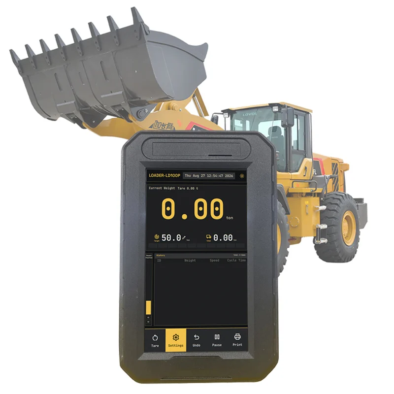
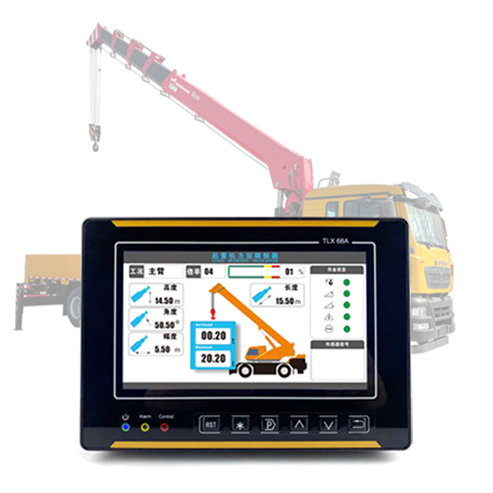
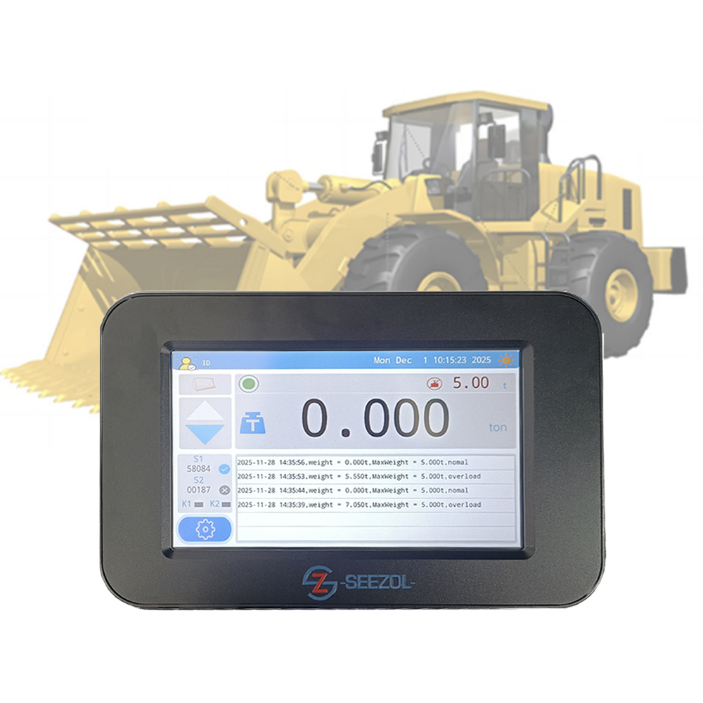
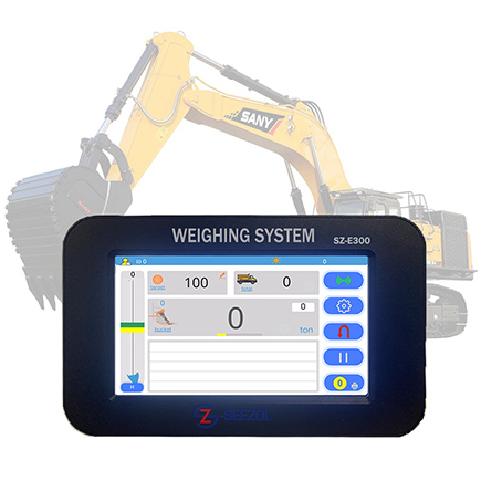
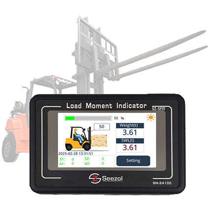
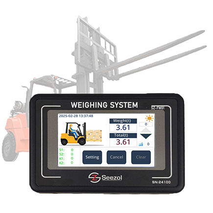
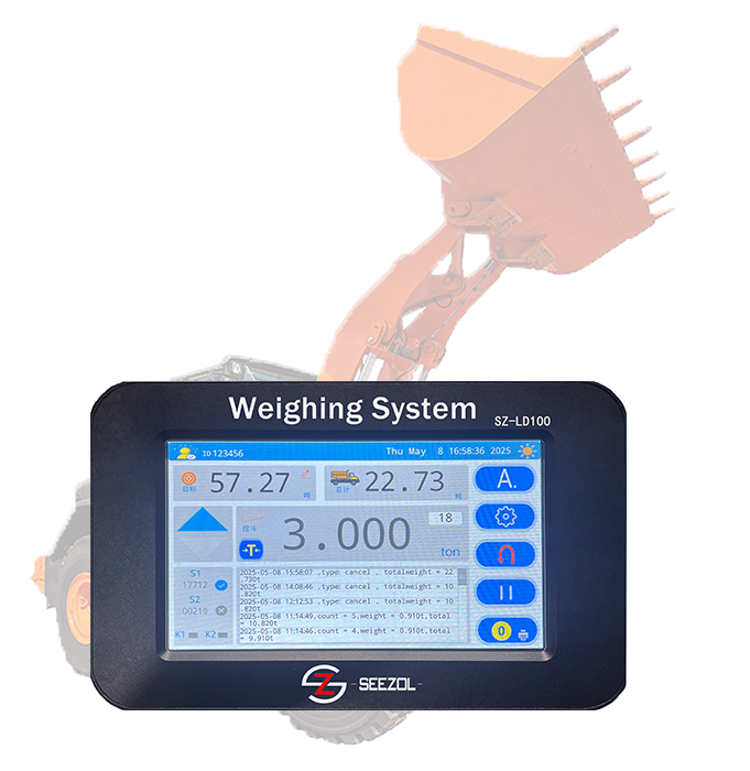
SeeZol fabrique des indicateurs de moment de charge, des limiteurs de capacité nominale et des systèmes de pesage embarqués destinés aux grues sur camion, aux grues à flèche articulée, aux grues sur chenilles, aux grues maritimes et aux engins de manutention. Un système type associe un capteur de charge sur le câble de levage, un capteur de longueur et d’angle sur la flèche, un boîtier de raccordement et un écran en cabine affichant la charge réelle, le rayon, la longueur de la flèche, l’angle et le pourcentage de la capacité nominale, avec des fonctions d’alerte préventive, de coupure automatique et d’enregistrement des événements. Les systèmes peuvent également être équipés d’un capteur de pression hydraulique lorsqu’il n’est pas possible d’installer une cellule de charge, d’un système de pesage embarqué pour les engins devant enregistrer leur chargement, et d’un système télématique lorsque la flotte a besoin de récupérer les données de l’engin.
Commencez par les pages produits : grue mobile LMI, grue à flèche articulée LMI, limiteur de charge de sécurité pour grue, capteur de pression hydraulique — ou Indiquez-nous le modèle de votre machine et la configuration de sa flèche et nos ingénieurs vous proposeront une chaîne de capteurs et une liste de configuration, généralement dans les 24 heures.
Sources
- Vertikal.net, Panne simultanée de deux grues, 25 septembre 2026 (comprend une vidéo de la chaîne affiliée à CBS montrant le deuxième échec) — lien
- CBS News Miami, Vendredi, des équipes s'affairent à retirer deux grues qui se sont effondrées sur un toit de Fort Lauderdale, tandis que les riverains s'interrogent sur les circonstances de l'accident - lien
- CBS News Miami, Une vidéo montre une deuxième grue s'effondrant sur le toit d'une maison à Fort Lauderdale ; aucun blessé n'est à déplorer - lien
- WPLG Local 10, Une grue s'est écrasée sur une maison de Fort Lauderdale après le renversement d'un camion-grue, 24 septembre 2026 (source des images de l'incident) — lien
- WPLG Local 10, Les opérations de nettoyage se poursuivent après le renversement de deux grues dans un quartier de Fort Lauderdale ; l'entreprise réagit, 25 septembre 2026 (déclaration de Cooper Crane, intervention de l'OSHA ; source des images de l'incident) — lien
- NBC 6 South Florida, Une deuxième grue s'est effondrée sur une maison à Fort Lauderdale alors qu'on tentait d'enlever la première - lien
- OSHA, 29 CFR 1926.1400 Champ d'application — confirmant que les camions-grues relèvent de la sous-partie CC — lien
- OSHA, 29 CFR 1926.1402 État du sol - lien
- OSHA, 29 CFR 1926.1415 Dispositifs de sécurité - lien
- OSHA, 29 CFR 1926.1417 Fonctionnement - lien
- SeeZol, aspects techniques : Explications sur les indices LMI, SLI, RCI et RCL, principaux indicateurs numériques des capteurs principaux, Liste de contrôle des paramètres de sélection LMI, Principes et composition du LMI, pesage embarqué vs indicateur de charge vs balance de charge, analyse des capteurs principaux
- SeeZol, conformité et applications : Pourquoi un indicateur de moment de charge est la mise à niveau la plus judicieuse pour votre grue sur camion; 5 erreurs courantes lors de l'étalonnage des LMI; LMI vs limiteurs de charge; Conformité aux normes de sécurité de l'UE relatives aux grues en 2026; Comment choisir un LMI adapté à votre machine