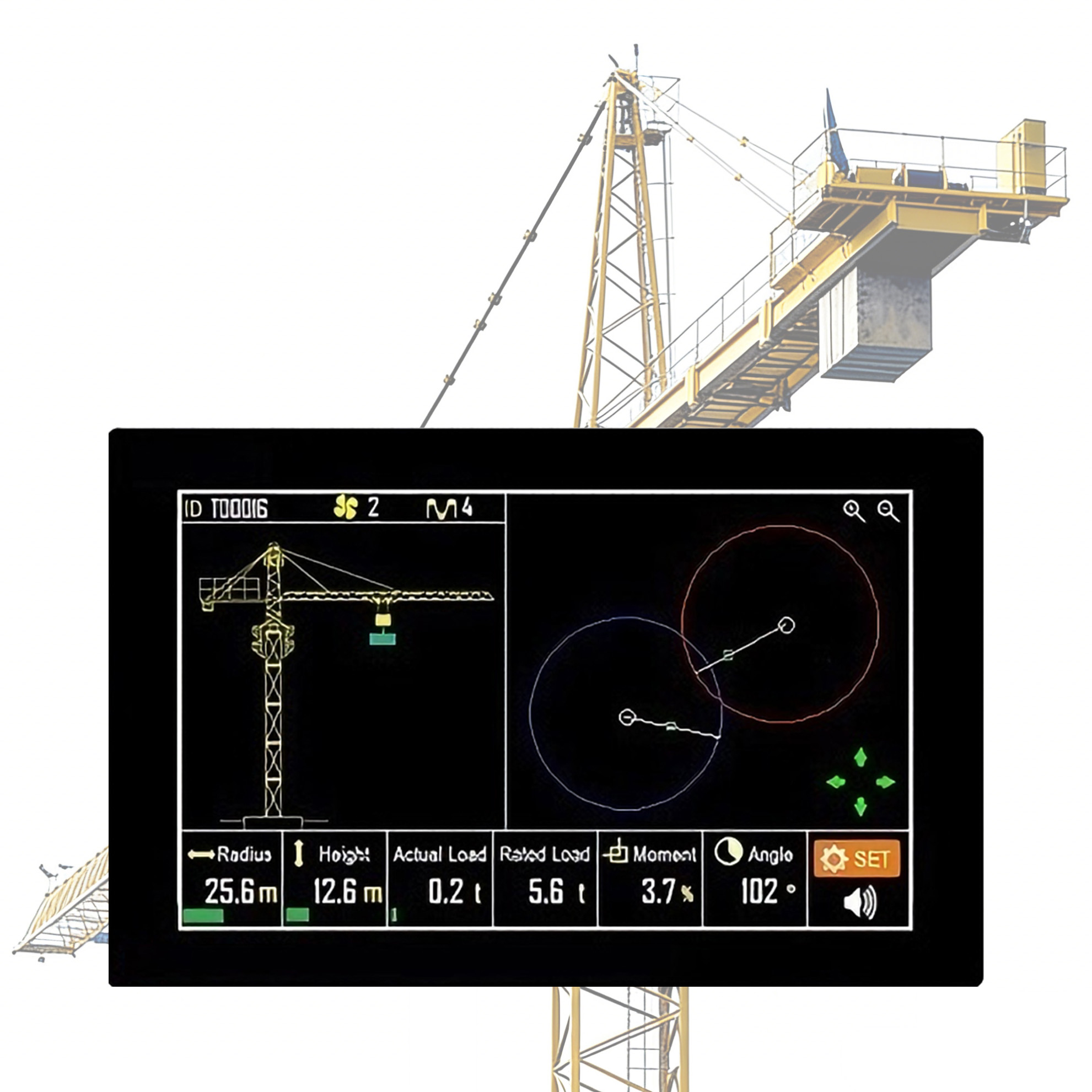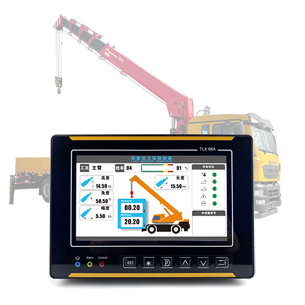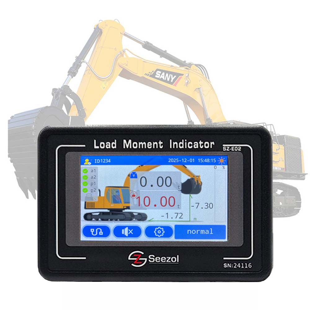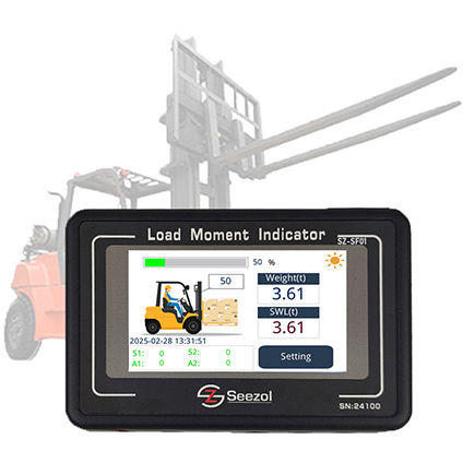
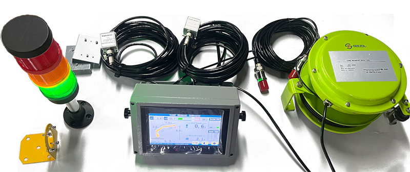
load moment indicator is an application system applied to crane equipment. So what is its working principle? Let’s talk about the working principle of the torque limiter.
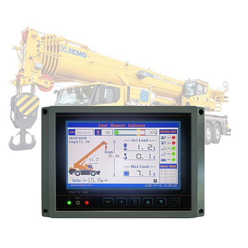
load moment indicator is composed of a sensor and a controller (instrument). When a hoisting machine lifts a heavy object, the weight, rotation angle and angle/amplitude are transmitted to the transmitter through the corresponding sensor. The transmitter converts and amplifies the signal, transmits it to the controller (instrument) through the RS485 interface in the system, and then enters the display screen to display relevant data after the CPU data processing of the instrument. At the same time, the instrument will measure the weight, rotation angle, The amplitude and other data are compared with the rated values of crane operating conditions preset by the program, and then actions such as display, alarm and control output are performed according to regulations.
After receiving the corresponding control signal, the crane can stop self-operation to the unsafe party without affecting other normal mechanism actions. At present, the limiter can play a role in limiting load protection for the crane.
Main Specifications:
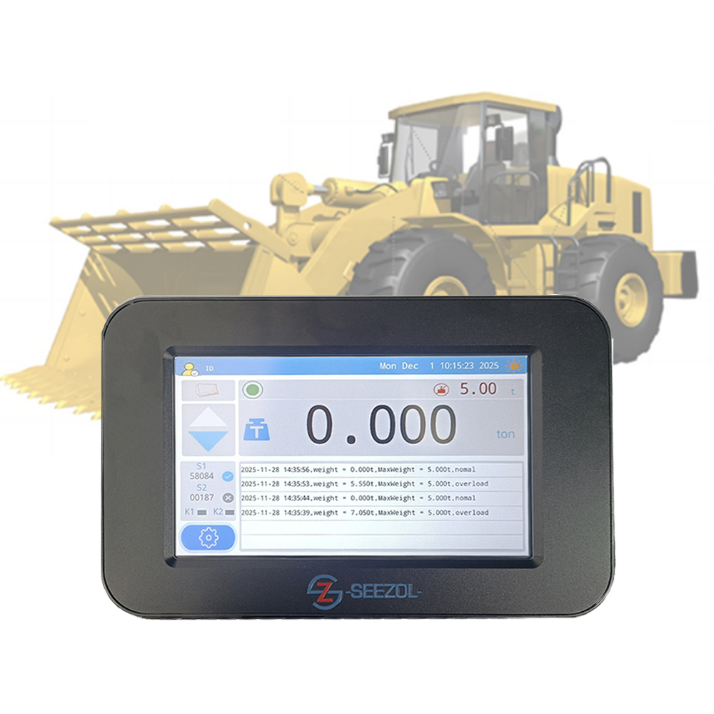
Scope of application: lifting equipment and other corresponding equipment that need to control the lifting torque
Weighing display error: ≤1%F.S, minimum display division value: 0.01t
Amplitude display error: ≤5cm, minimum display division value: 0.01m
Height display error: ≤5cm, minimum display division value: 0.01m
System action error: ≤3 %F.S
Alarm mode: (the work plan can also be provided by the user)
Lifting weight pre-alarm:
The current lifting weight is greater than or equal to 90% of the current rated value, and the buzzer sounds intermittently
Current lifting capacity ≥ 105% of the current rated value, with a delay of 2 seconds to output the control signal, which is used to cut off the ascent control loop and the amplification control loop, and emit a continuous alarm
Lifting weight alarm (immediately):
The current lifting capacity is greater than or equal to 120% of the current rated value, and the control signal is immediately output to cut off the ascending control loop and the amplifying control loop, and emit a continuous alarm sound
Note: Lifting weight “delay alarm” and “immediate alarm” control output signals can either be output independently or integrated into the same point output.
Amplitude alarm:
When the current amplitude ≥ the current rated value, the control signal will be output immediately, which is used to cut off the amplitude control loop and emit a continuous alarm sound
Releasing the alarm:
When the display value of each part is restored to the rated value of the current corresponding mechanism within the safety range, the alarm will stop, the output control signal will be automatically released after 2 seconds, and the cut off action control loop will resume normal operation.
Working environment: temperature, -40~+60℃ relative humidity, 45%-95%
Sensor protection level: IP65
Power supply voltage: AC380V (+10%, -15%), or AC220V (+10%, -15%)
Control output: relay contact switch value, capacity AC380V, 2.5A.
The number of control output points (normally open and normally closed) and control objects can be customized by the user.
Data communication output: RS485, RS232, PROFIBUS, etc.
Analog signal output: 0-10V, 4-20mA, etc.
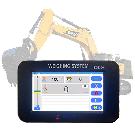
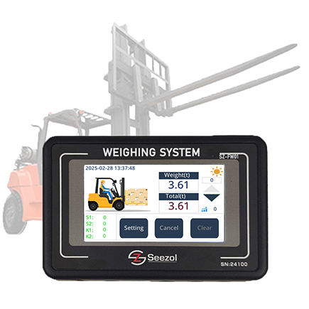
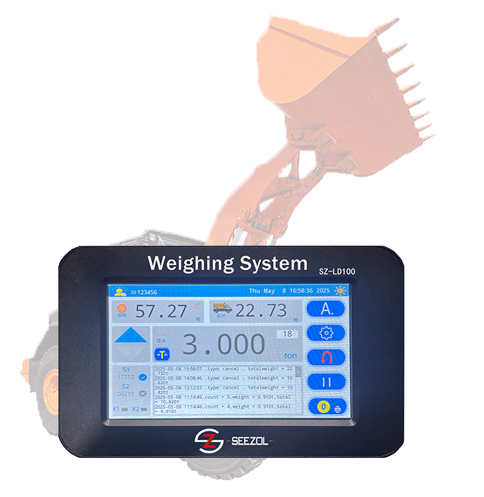
Instrument display mode: LED and LCD digital display or touch screen menu display.