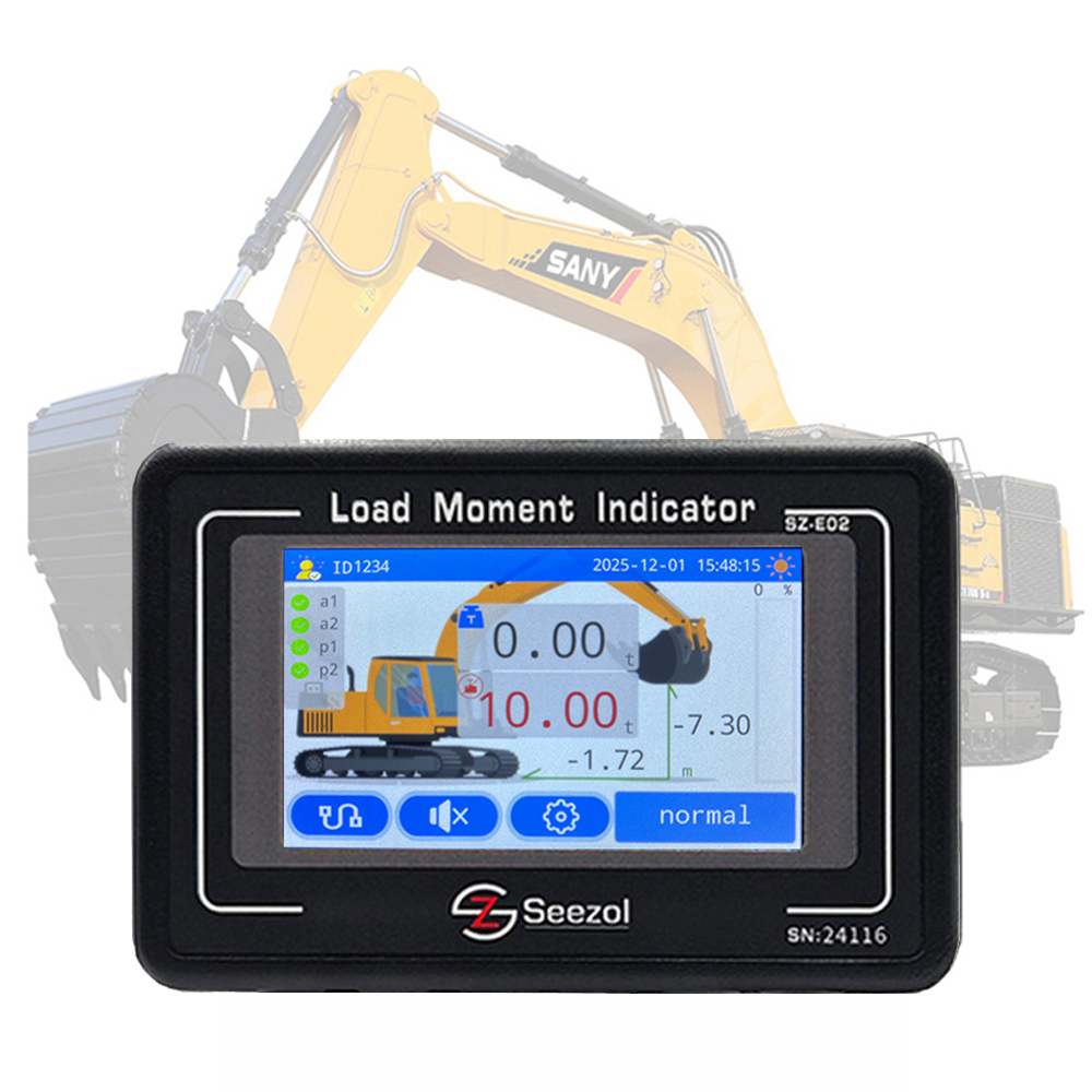
1. Overview
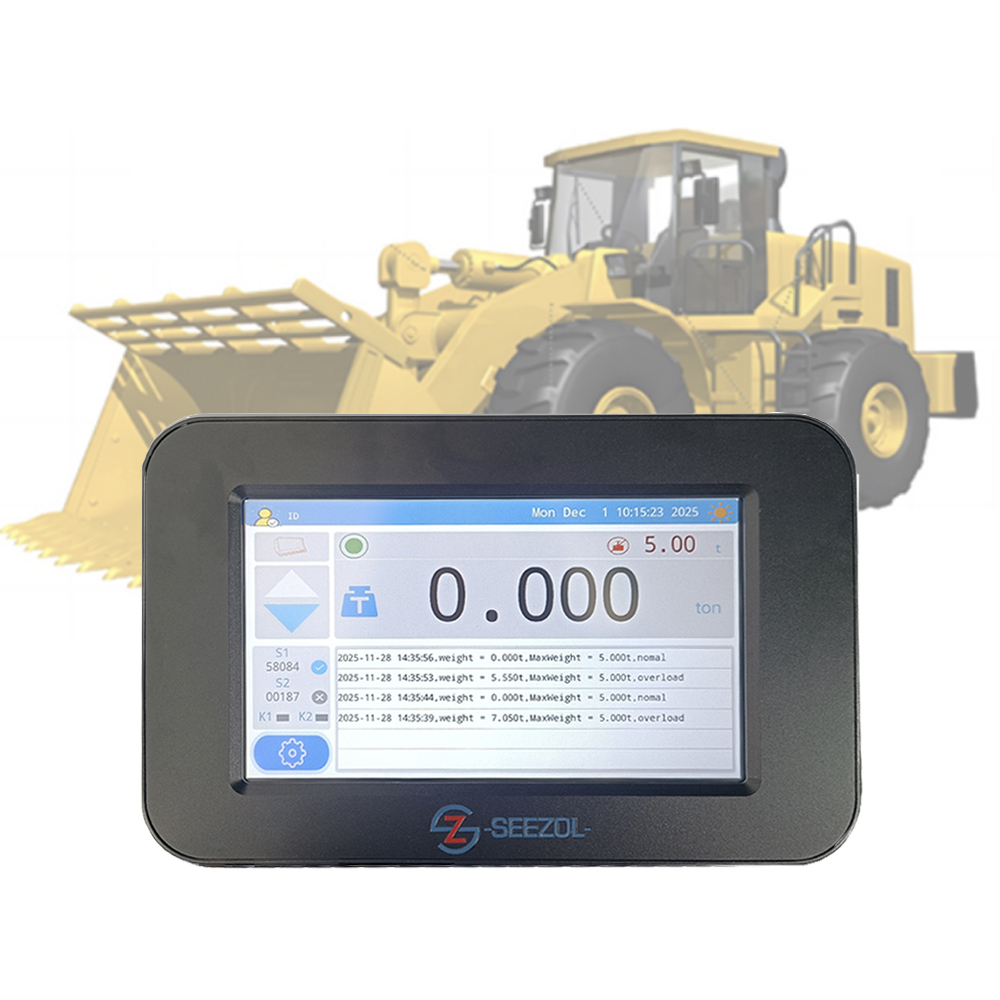
The underground ore truck weighing system is a key system for achieving real-time monitoring of loading volume and improving transportation efficiency and safety in mining operations.This solution, based on strain gauge weighing technology, utilizes three weight sensors installed on the ore truck’s beam. This system, combined with a host weighing system and CAN bus communication, enables precise collection, calculation, and transmission of weight data. Suitable for the harsh environments of underground mines, the system supports real-time data display and integrated control, contributing to the development of smart mines.
2.System Principle
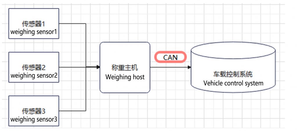
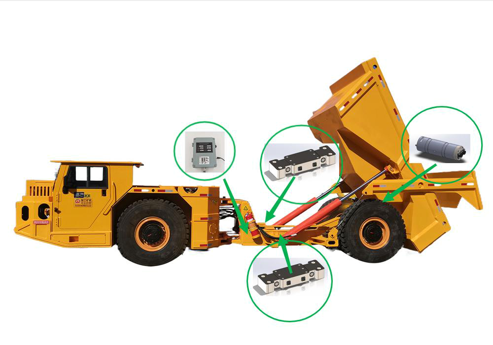
Sensing Layer: Three strain gauge load cells are installed at key stress points on the ore truck’s beam, detecting beam deformation in real time and converting it into electrical signals.
Processing Layer: The weighing host receives the sensor signals and calculates the net weight using dynamic algorithms (such as filtering and temperature compensation), eliminating interference from vehicle motion.
Transmission Layer: The processed weight data is transmitted to the ore truck’s control system via the CAN bus (CAN-OPEN protocol), enabling integrated display and control.
3. System composition
| Components | Specification/Model | Quantity | Remarks |
| Weighing sensor | SZ-DB30T-30MC (30-ton capacity) | 3 | Chip-type, IP68 protection, suitable for beam mounting |
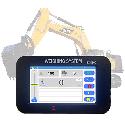
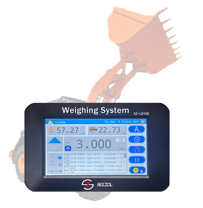
| Weighing Host | SZ-E02 Series | 1 | 12-24V DC power supply, supports CAN-OPEN protocol |
| Cable | Specialized shielded cable | On request | Abrasion-resistant and corrosion-resistant |
| CAN bus interface | Standard CAN 2.0B | – | Integrated into the host, 250kbps transmission rate |
4. Sensor installation location
Installation point
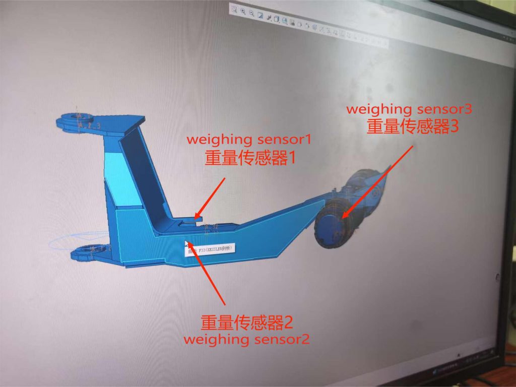
Front Frame Location (2 Sensors):
- Location: On the left and right fenders or webs of the frame above the front axle, approximately 1/4 vehicle length from the front axle support point.
- Reason: The front section carries the initial load, avoiding interference with the steering mechanism and ensuring stability.
- Mounting Method: Secure the sensor base to the frame using high-strength bolts, ensuring a tight fit.
Rear Axis (1 sensor):
- Location: At the rear of the vehicle, where the passenger compartment connects to the frame.
- Reason: Primary load-bearing area, effectively reflects overall load distribution.
- Mounting Method: The sensor directly replaces the load-bearing axle.
Installation Notes
- Surface Preparation: The mounting point must be polished and smooth to ensure there is no gap between the sensor and the beam.
- Error-Proofing Design: The left and right sensors are installed symmetrically to compensate for eccentric load errors.
- Environmental Protection: A dust cover is installed to prevent impact with rocks and erosion by muddy water.
5. Technical parameters
- Rated load: 90 tons (compatible with 40-80 ton vehicles)
- Weighing accuracy: ≤±2% F.S. (static)
- Operating temperature: -30°C to +70°C
- Communication protocol: CAN-OPEN (customizable with J1939)
- Protection level: IP68 for sensor, IP66 for host
- Power requirement: 24V DC (vehicle compatible)
6. Integration and Communication
- Data flow: Sensor → Scale host → CAN bus → Vehicle control system (e.g., instrument panel or PLC).
- Function expansion: Supports overload alarms, load statistics, and remote monitoring (via fleet management systems).
7. Feasibility advantage
- Resource Optimization: Only three sensors are required, reducing costs and installation complexity.
- Real-time: The CAN bus ensures low-latency data transmission, suitable for dynamic operations.
- Reliability: Based on a proven solution (referring to the off-highway wide-body vehicle case), it is suitable for underground environments.