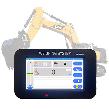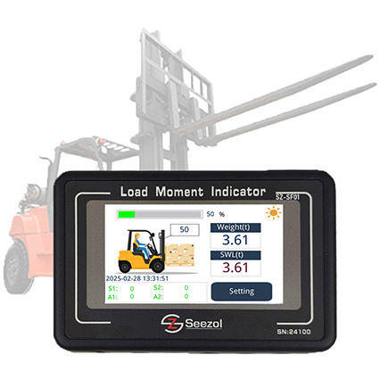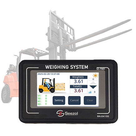
1. Обзор
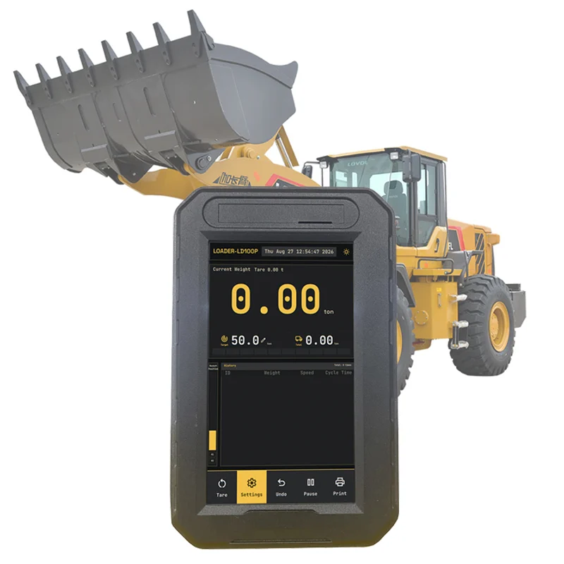
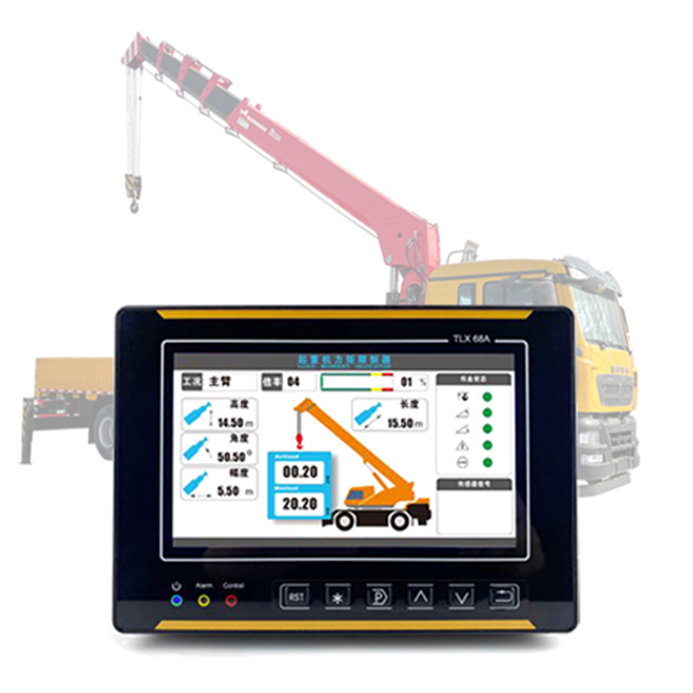
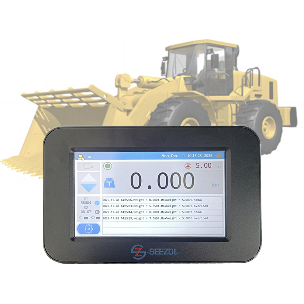
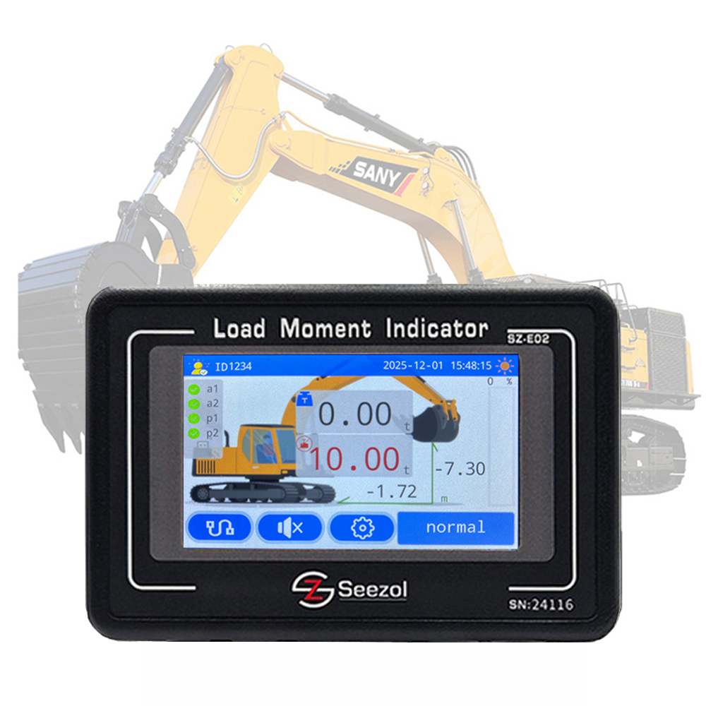
The Индикатор момента нагрузки (LMI, также называемый ограничителем момента) и Встроенная система взвешивания являются критически важными устройствами, обеспечивающими безопасную и эффективную работу экскаваторов, погрузчиков, автокранов и другой гидравлической техники. Принцип измерения технологии SeeZol заключается в установке датчиков давления масла в гидравлическом контуре для считывания рабочего давления в цилиндре в режиме реального времени, а затем преобразовании этого значения — с помощью откалиброванного алгоритма — в текущую массу груза и результирующий момент, что позволяет осуществлять предупреждение о перегрузке и ограничение нагрузки.
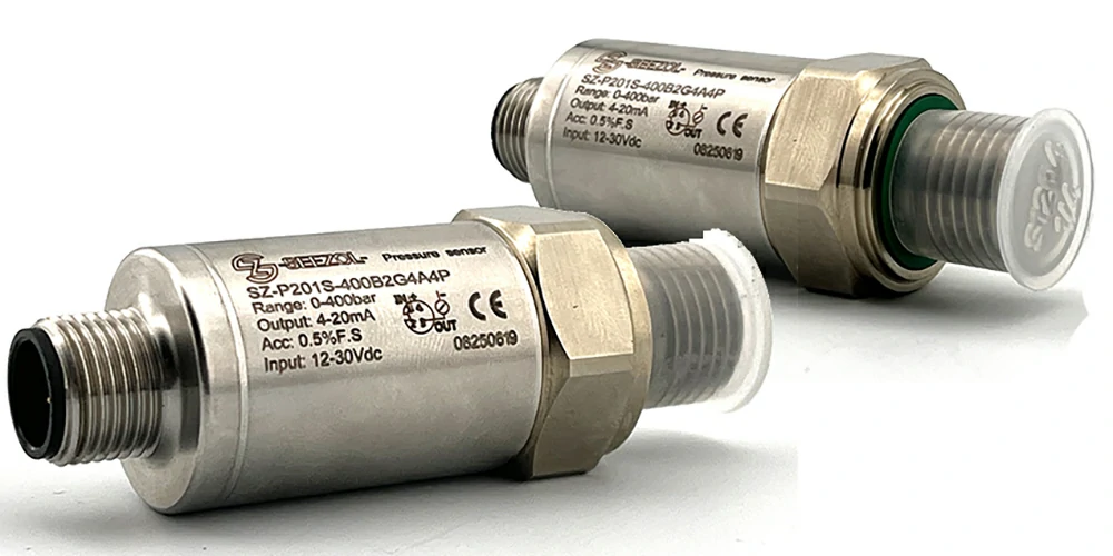
Датчики давления масла SeeZol поставляются с унифицированным интерфейсом 1/4 дюйма. Благодаря такой стандартизации работа на месте сводится к соединению 1/4-дюймового конца датчика с гидравлическим разъемом машины, что значительно упрощает выбор модели и управление запасными частями.
2. Три способа монтажа в зависимости от типа соединения гидравлических линий
В зависимости от способа соединения гидравлических магистралей машины монтаж датчика давления масла в полевых условиях подразделяется на три категории.
2.1 Монтаж тройниковых соединений (машины с резьбовыми соединениями)
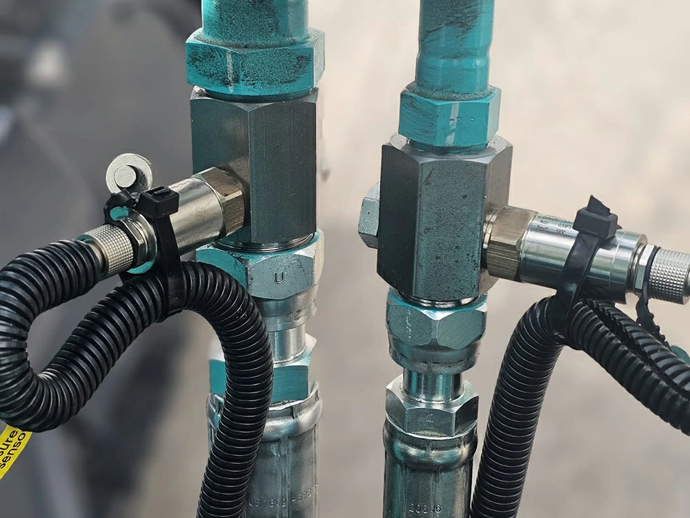
Применимо к: машины, гидравлические трубопроводы которых соединяются резьбовыми стыковыми соединениями.
Принцип: На исходном резьбовом соединении устанавливается тройник, который параллельно датчику давления масла вводится в контур для отбора проб давления без прерывания основного потока.
Шаги:
- Измерьте резьбу исходного соединения. Это самый важный этап — необходимо точно измерить параметры обеих исходных резьб (метрическая M, BSP/G, NPT и т. д. с указанием точных размеров) и выбрать тройник, верхний и нижний концы которого точно соответствуют этим параметрам.
- Поработайте с боковым портом. В боковое отверстие тройника можно либо установить переходник 1/4 для прямого подключения датчика давления масла, либо приварить коленчатый фитинг 1/4, поставляемый компанией SeeZol, перед тем как ввинтить датчик.
Примечание: Выбор резьбы должен основываться на результатах измерений; неправильный выбор приводит к выходу уплотнения из строя.
2.2 Монтаж фланцев (машины с зажимным креплением / быстроразъемными соединениями)
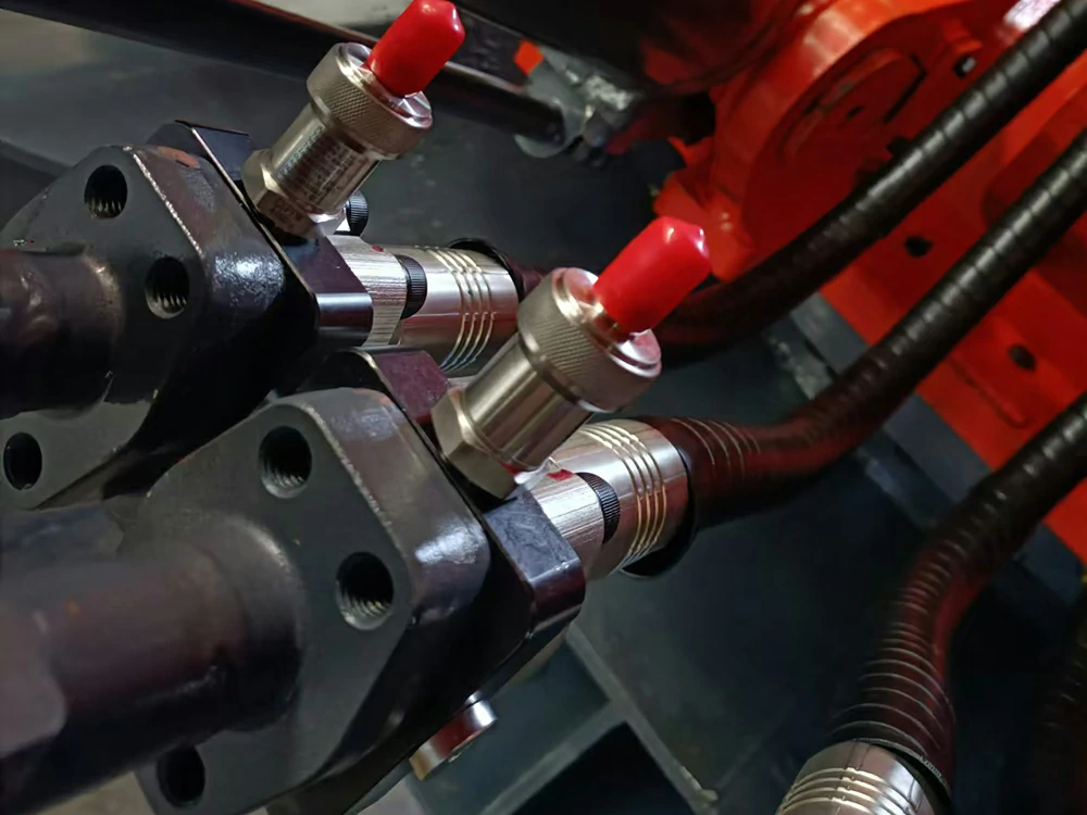
Применимо к: машины, гидравлические трубопроводы которых соединяются с помощью зажимных (быстроразъемных) соединений.
Принцип: В месте зажимного соединения предусмотрен специальный фланец; на стороне фланца имеется отведённое гнездо для датчика размером 1/4.
Шаги:
- Измерьте расстояние между центрами четырёх болтов зажима и проверьте размер резьбы болтов.
- Выберите или изготовьте на заказ подходящий фланец на основе полученных измерений; на его боковой поверхности имеется встроенный патрубок 1/4 для датчика давления масла.
Примечание: Данный метод не изменяет исходную конструкцию уплотнения хомута — он лишь фиксирует фланец с помощью отверстий для болтов хомута, обеспечивая устойчивое крепление, которое при этом легко снимается для проведения технического обслуживания.
2.3 Установка взрывозащищенного клапана (машины с предохранительными клапанами)
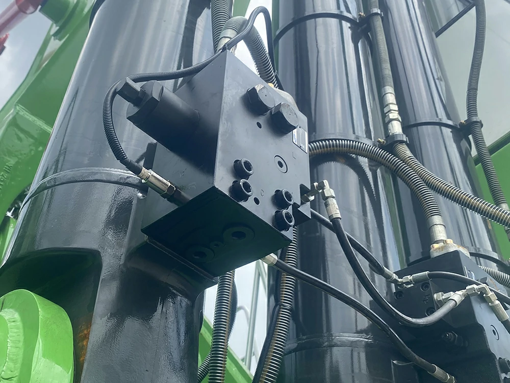
Применимо к: машины, гидравлические линии которых оснащены взрывозащитным клапаном (также называемым предохранительным клапаном или уравнительным клапаном).
Принцип: В взрывозащищённом клапане обычно предусмотрен основной порт для испытания под давлением; датчик давления масла вкручивается напрямую, без необходимости использования сложных переходников.
Шаги:
- Найдите главный патрубок клапана для испытания под давлением.
- Если порт представляет собой стандартный разъем 1/4, прикрутите датчик давления масла непосредственно к нему.
- Если разъем нестандартный, сначала установите переходник 1/4, а затем подключите датчик.
Примечание: Это самый простой метод, и, поскольку точка тестирования является точкой реального давления в системе, качество сигнала и скорость отклика оставляют желать лучшего.
3. Обязательное правило: размеры соединителей должны точно совпадать
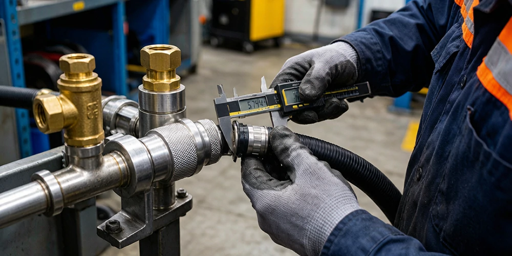
Какой бы метод ни использовался, первое железное правило гласит: все размеры соединителей должны точно совпадать. Гидравлическая магистраль представляет собой герметичную систему высокого давления, и при любом отклонении от номинальных размеров категорически запрещается устанавливать детали с принудительным затягиванием. Даже при принудительной резьбе с минимальным несоответствием резьба будет затянута не до конца, что приведет к нарушению герметичности и утечке масла. Утечка не только искажает результаты измерения давления и снижает точность измерений, но и может привести к разбрызгиванию жидкости под высоким давлением, создавая угрозу безопасности; кроме того, принудительная установка легко повреждает оригинальные фитинги оборудования, что приводит к дорогостоящему ремонту. Поэтому при любом сомнении в размерах всегда следуйте следующей последовательности действий: сначала измерить, потом выбрать, а в конце установить.
4. Расположение и ориентация датчика
Положение и ориентация определяются с учетом удобства прокладки кабеля сигнала давления масла в соответствии со следующими принципами:
- Предпочесть крепление с внутренней стороны — разместите датчик на внутренней стороне конструкции, чтобы снизить риск повреждения при ударе.
- Тщательно оцените рабочий диапазон стрелы (рукава) во время эксплуатации; убедитесь, что ни корпус машины, ни посторонние препятствия не могут задеть датчик или кабель в любом положении.
- Расположите датчик так, чтобы облегчить вывод кабеля, и не допускайте его намотки на вращающиеся или выдвигающиеся детали.
5. Защита и прокладка сигнального кабеля
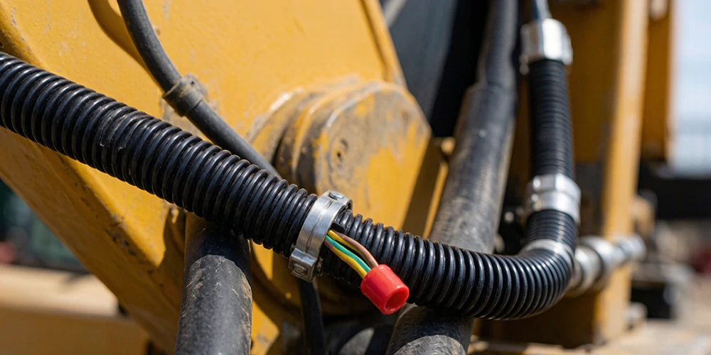
Условия эксплуатации на строительных площадках суровы, и кабели легко повреждаются; обеспечьте их защиту следующим образом:
- Проложите сигнальный кабель внутри гофрированный кабелепровод по всей поверхности для обеспечения устойчивости к истиранию, воздействию масел и ударам.
- Проложите маршрут вдоль собственных гидравлических шлангов машины, используя имеющиеся каналы и точки крепления — так получится аккуратно, и вероятность отсоединения будет меньше.
- Уйти необходимый запас чтобы при подъеме/опускании стрелы, при котором шланги растягиваются, сигнальный кабель не натягивался и не обрывался.
6. Ограничения и дополнительные примечания
- Данное руководство составлено на основе выводов аудита компании SeeZol Technology по типовым моделям; специальные модели или модифицированные транспортные средства следует оценивать с учетом их фактических гидравлических контуров.
- После установки на главный испытательный патрубок взрывозащищённого клапана убедитесь, что это не влияет на исходные функции балансировки и блокировки клапана.
- После монтажа перед вводом системы измерения нагрузки в эксплуатацию необходимо провести испытание на удержание давления и проверку герметичности.
7. Отказ от ответственности
Настоящее техническое руководство составлено компанией SeeZol Technology исключительно для использования персоналом, занимающимся монтажом и техническим обслуживанием. Установка датчиков давления связана с гидравлическими системами высокого давления; ненадлежащее обращение может привести к травмам или повреждению оборудования. Фактические работы должны выполняться квалифицированным персоналом в строгом соответствии с руководством по эксплуатации соответствующей машины и применимыми нормами безопасности. Компания SeeZol Technology не несет прямой ответственности за любые последствия, возникшие в результате несоблюдения правил эксплуатации.