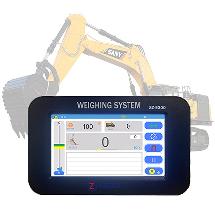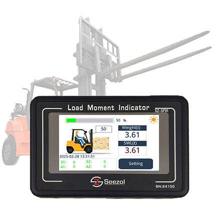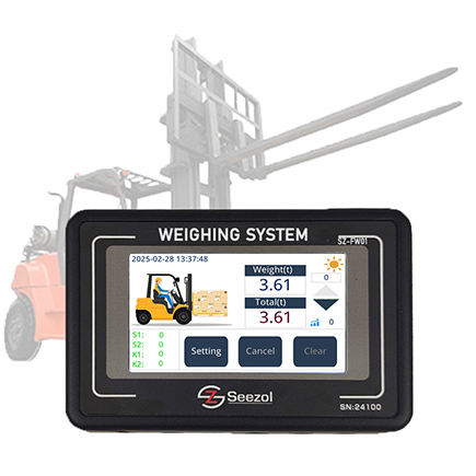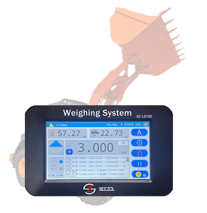
Aperçu des principes, des distinctions, des relations et des domaines d'application
[SeeZol Technology]
[CE, ISO, spécialiste de la sécurité des grues]
[sales@seezol.com]
Mise à jour : 4 août 2026
Avertissement / Champ d'application : Le présent article est une analyse technique destinée exclusivement à des fins pédagogiques et de référence. Il ne constitue en aucun cas des spécifications de conception d'équipements, des procédures opérationnelles ou des conseils en matière de conformité réglementaire. Tous les paramètres, seuils et références réglementaires doivent être vérifiés à la lumière des manuels du fabricant de l'équipement concerné et des réglementations locales applicables avant toute prise de décision technique ou opérationnelle.
Résumé
Avec la complexité croissante des chantiers d'ingénierie modernes, l'exploitation en toute sécurité des équipements mécaniques de grande envergure, tels que les grues, est devenue un élément essentiel pour garantir l'avancement des projets. En tant que deux dispositifs de protection essentiels pour les grues, l'évolution technologique et la logique d'application de LIndicateurs de moment de charge (LMI) et Limiteurs de charge ont un impact direct sur la sécurité opérationnelle. Cet article passe en revue les principes de base des indicateurs de moment de charge et des limiteurs de charge, fournit une analyse approfondie des différences techniques entre les dispositifs mécaniques et électroniques, clarifie les distinctions essentielles entre leurs concepts, leurs fonctions et leur logique de commande, et explore leurs relations d'interaction dans des conditions de travail spécifiques ainsi que leur état actuel d'application dans des domaines tels que la construction et les ports. Les recherches indiquent qu’une compréhension précise et une application synergique de ces deux technologies de limitation revêtent une grande importance pour améliorer le niveau de sécurité intrinsèque des équipements.
Mots-clés : Indicateur de moment de charge (LMI) ; Limiteur de charge ; Dispositifs de sécurité ; Principes de fonctionnement ; Synthèse
Nomenclature / Abréviations
| Symbole / Terme | Définition / Unité |
| LMI | Indicateur de moment de charge |
| W | Poids de la charge à soulever (t ou kg) |
| r | Rayon d'action / bras de levier (m) |
| M_réel | Moment de levage réel (kN·m ou t·m) |
| Classé M | Couple de levage nominal au rayon actuel (kN·m ou t·m) |
| θ | Angle de la flèche (°) |
| L | Longueur de la flèche (m) |
| n | Facteur de passage des câbles métalliques (sans dimension) |
| ISO 10245 | Série de normes ISO relative aux dispositifs de limitation et de signalisation pour grues |
| GB/T 12602 | Norme chinoise : Dispositifs de protection contre les surcharges pour grues |
Introduction
Dans les systèmes industriels modernes, les grues sont largement utilisées dans le génie civil, la construction de ponts, la logistique portuaire et l'aérospatiale, où elles accomplissent des tâches essentielles dans la manutention de matériaux lourds. Cependant, les opérations de levage se caractérisent généralement par des risques élevés, des changements dynamiques et des conditions de travail complexes. Des accidents catastrophiques, tels que le renversement d'équipements et la rupture de flèches, se produisent de temps à autre. Conformément aux réglementations de sécurité applicables — notamment la norme ISO 10245 (Grues — Dispositifs de limitation et d'indication), la norme GB/T 12602 (Dispositifs de protection contre les surcharges pour grues), EN 13000 (Grues mobiles), ANSI/ASME B30.5 (Grues mobiles et locomotives), et OSHA 29 CFR 1926 sous-partie CC (Grues et derricks dans le secteur de la construction) —, les grues doivent être équipées de dispositifs de sécurité complets, parmi lesquels les indicateurs de moment de charge (LMI) et les limiteurs de charge constituent la dernière ligne de défense contre la surcharge de l’équipement.
Bien que ces deux dispositifs soient des dispositifs de sécurité destinés à prévenir les surcharges, il existe souvent, tant dans les applications pratiques de l’ingénierie que dans la recherche universitaire, une confusion cognitive qui consiste à assimiler les « indicateurs de moment de charge » aux « limiteurs de charge ». En réalité, un indicateur de moment de charge se concentre sur le produit de la force et du bras de levier, ce qui implique la stabilité et la résistance structurelle de l’équipement ; tandis qu’un limiteur de charge se concentre uniquement sur l’amplitude de la force gravitationnelle de la charge. Grâce au développement de la technologie des capteurs et des algorithmes de contrôle intelligents, ces deux dispositifs ont évolué, passant de structures purement mécaniques à l’origine à des systèmes électroniques intelligents de haute précision.
Cet article a pour objectif de faire le point de manière systématique sur leurs principes techniques, leurs différences fonctionnelles et leurs mécanismes de synergie, à travers une analyse documentaire et une étude des principes, afin de fournir des repères théoriques pour la conception et l'utilisation en toute sécurité des grues.
Méthodologie
Cette étude s'appuie sur un cadre de comparaison structuré couvrant quatre dimensions : (1) le principe physique et l'évolution technologique, (2) la logique de commande et l'étendue des variables, (3) les relations de couplage dans des conditions de fonctionnement variables, et (4) les modèles d'application sur le terrain. L’analyse s’appuie sur des normes publiées (ISO, GB, EN, ASME), des publications évaluées par des pairs et des observations de cas représentatifs. Les exemples quantitatifs utilisent des paramètres illustratifs à des fins pédagogiques ; les valeurs réelles doivent respecter les manuels spécifiques aux équipements et les réglementations locales.
1. Principes et évolution technologique des indicateurs de moment de charge
Le principe fondamental d'un indicateur de moment de charge consiste à empêcher le renversement ou la défaillance structurelle d'une grue, provoqués par un moment de levage dépassant la valeur nominale. Sur le plan technique, sa mise en œuvre a principalement évolué, passant de systèmes mécaniques à des systèmes électroniques.
1.1 Principe de fonctionnement des indicateurs de moment de charge mécaniques
Les premiers indicateurs mécaniques de moment de charge reposaient principalement sur des structures purement mécaniques telles que des leviers, des ressorts et des contrepoids. Leur principe de fonctionnement repose sur l'équation d'équilibre des moments. Lorsque le moment de renversement généré par la force exercée sur la flèche de levage dépasse le moment d'équilibre généré par la précontrainte du ressort ou le contrepoids, le mécanisme mécanique se déplace, ce qui déclenche un interrupteur de fin de course qui coupe l'alimentation électrique.
Les dispositifs mécaniques se caractérisent par une structure simple, ne nécessitent aucune alimentation électrique externe et possèdent une forte résistance aux interférences, ce qui explique leur utilisation généralisée dans les premières grues à tour. Cependant, leurs inconvénients sont également évidents : faible précision (fortement affectée par l’usure mécanique, la fatigue des ressorts et les frottements) ; fonctionnalité unique (incapacité à afficher des paramètres en temps réel) ; et réglages complexes, ce qui les rend difficiles à adapter à des opérations complexes impliquant de multiples conditions de travail et facteurs de palanage. C’est pourquoi ils sont progressivement abandonnés dans les équipements de levage haut de gamme.
1.2 Principe de fonctionnement des indicateurs électroniques de couple de charge
Les indicateurs électroniques modernes de moment de charge (LMI) sont des systèmes intelligents intégrant la technologie des capteurs, celle des microprocesseurs et celle du contrôle automatique. Leur principe de fonctionnement repose sur l’utilisation de capteurs placés à la base de la flèche de levage, sur les mécanismes de variation d’angle et sur les mécanismes de levage pour recueillir en temps réel des paramètres tels que le poids de la charge, la longueur de la flèche, le rayon d’action (angle de la flèche) et les coefficients de sécurité des câbles métalliques.
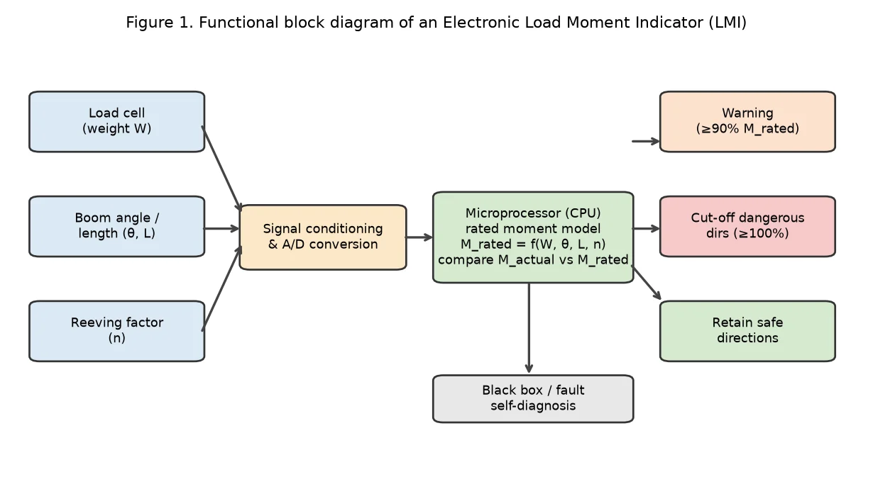
Figure 1. Schéma fonctionnel d'un indicateur électronique de couple de charge (LMI).
L'unité centrale de traitement (CPU) utilise les données collectées et des modèles mathématiques prédéfinis pour calculer en temps réel le couple de levage réel dans les conditions de travail actuelles, puis le compare à la courbe caractéristique du couple de levage nominal stockée en mémoire. Lorsque le couple réel atteint 90% de la valeur nominale, le système émet un avertissement ; lorsqu’il atteint 100%, il coupe automatiquement les circuits de commande des directions dangereuses (par exemple, levage, abaissement de la flèche) tout en conservant la capacité de fonctionner dans les directions sûres (par exemple, abaissement de la charge, relevage de la flèche).
Les indicateurs électroniques de couple de charge se caractérisent par une grande précision (erreurs généralement maîtrisées à ±5% conformément aux exigences d’étalonnage de la norme ISO 10245), de nombreuses fonctionnalités (enregistrement « boîte noire » et autodiagnostic des défauts) et une grande adaptabilité. Ces dernières années, grâce aux progrès de l’intelligence artificielle, certains systèmes avancés ont intégré la fonction « apprentissage et reproduction », qui permet d’enregistrer les trajectoires de manœuvre d’opérateurs expérimentés afin d’assurer un contrôle optimisé en temps réel du couple lors des opérations automatisées.
Tableau 1. Comparaison entre les indicateurs de performance de ligne (LMI) mécaniques et électroniques
| Aspect | LMI mécanique | Informations sur le marché du travail (IMT) sous forme électronique |
| Mécanisme central | Leviers, ressorts, contrepoids | Capteurs + processeur + modèle logiciel |
| Alimentation électrique requise | Aucun (passif) | Alimentation CC externe requise |
| Précision | Faible (sensible à l'usure et à la fatigue) | Élevé (±51 TP4T, valeur typique) |
| Affichage en temps réel | Non | Oui (poids, rayon, % de la puissance nominale) |
| Prise en charge de plusieurs pathologies | Mauvais (configuration fixe) | Excellent (changement dynamique de courbe) |
| Boîte noire / diagnostics | Indisponible | Fonctionnalité standard |
| Applications typiques | Grues à tour anciennes | Grues mobiles, grues à tour et grues portuaires modernes |
| Coût | Coût initial moins élevé | Plus élevé, mais en baisse |
Exemple détaillé — Calcul du moment LMI :
Données : W = 8,0 t (mesurée par le capteur de charge), r = 12 m (rayon d'action mesuré par le capteur d'angle de flèche), la capacité nominale à r = 12 m est de 4,2 t (d'après la courbe caractéristique enregistrée).
M_réel = W × r = 8,0 × 12 = 96 t·m
M_rated = 4,2 × 12 = 50,4 t·m
Rapport = M_réel / M_nominal = 96 / 50,4 ≈ 190%
Résultat : 190% > 100% → Le système interrompt immédiatement les mouvements dangereux. (Valeurs à titre indicatif ; les courbes nominales réelles varient selon le modèle de grue.)
2. Principes et méthodes de mise en œuvre des limiteurs de charge
La fonction principale d'un limiteur de charge (également appelé « limiteur de poids de charge ») est d'empêcher les grues de soulever des objets dont la charge dépasse la charge nominale, évitant ainsi la rupture des câbles métalliques, la surchauffe du moteur ou la déformation plastique de la structure.
2.1 Principe des limiteurs de charge à jauges de contrainte
La technologie des jauges de contrainte est actuellement la méthode de détection de charge la plus répandue. Son composant principal est la jauge de contrainte à résistance, qui est généralement collée sur les éléments structurels porteurs de la grue (tels que les axes et les tirants) ou sur des corps élastiques servant de capteurs dédiés. Selon la loi de Hooke, dans la plage élastique, la déformation du matériau est proportionnelle à la contrainte. Lorsqu’une charge lourde est soulevée, le corps élastique subit une microdéformation, ce qui entraîne une variation de la valeur de résistance de la jauge de contrainte collée. Un pont de Wheatstone convertit cette variation de résistance en un signal de tension, qui est ensuite amplifié et converti par un convertisseur analogique-numérique (A/N), permettant ainsi au processeur de calculer le poids réel.
Cette méthode se caractérise par une grande précision de mesure, une réponse dynamique rapide et un encombrement réduit, ce qui explique son utilisation répandue dans les ponts roulants, les portiques et les grues à tour. Elle présente toutefois l'inconvénient d'être sensible à la température, ce qui nécessite une compensation thermique, et la position d'installation a une incidence significative sur la précision des mesures.
Exemple pratique — Calcul de la sortie d'une jauge de contrainte :
Données : facteur de jauge du capteur GF = 2,0, tension d'excitation V_ex = 10 V, déformation à pleine échelle ε_fs = 2 000 με (microdéformation), sortie du pont ΔV/V_ex = GF × ε / 4 (approximation du quart de pont).
Pour une charge de 80% : ε = 1 600 με → ΔV = 10 × (2,0 × 1 600 × 10⁻⁶ / 4) = 8,0 mV
Après amplification avec un gain G = 500 → V_out = 4,0 V → Le processeur attribue une valeur de pondération.
(À titre d'exemple ; les circuits réels peuvent utiliser une configuration en pont complet pour une meilleure linéarité.)
2.2 Autres technologies de limitation de charge
Outre les jauges de contrainte, les méthodes hydrauliques et capacitives constituent également des technologies courantes de limitation de charge. Les dispositifs hydrauliques exploitent la relation linéaire entre la pression d'huile et la charge, en déduisant la charge à partir de la pression du système hydraulique. Ils sont souvent utilisés dans les circuits des stabilisateurs ou des vérins hydrauliques des grues mobiles, et se caractérisent par une forte résistance aux surcharges et une bonne tolérance aux environnements difficiles. Les dispositifs capacitifs mesurent le poids selon le principe selon lequel les variations de l'espacement entre les plaques ou de la constante diélectrique entraînent des variations de capacité. Ils conviennent à la mesure sans contact ou à des environnements particuliers, mais leur stabilité en présence de fortes interférences électromagnétiques est légèrement inférieure à celle des jauges de contrainte.
Tableau 2. Comparaison des technologies de limiteurs de charge
| Technologie | Principe | Précision | Avantages | Inconvénients | Exemple d'application |
| Jauge de contrainte | Variation de la résistance selon la loi de Hooke (pont de Wheatstone) | ±0,5–11 TP4T | Haute précision ; réponse rapide ; compact | Sensible à la température ; montage critique | Grues à tour, grues à portique et ponts roulants |
| Hydraulique | Pression d'huile ∝ charge (loi de Pascal) | ±2–3% | Robuste ; résistant aux surcharges ; simple | Précision moindre ; risque de fuite de liquide | Stabilisateurs/vérins de grues mobiles |
| Capacitif | Variation de la capacité en fonction de l'espacement entre les plaques et du diélectrique | ±1–2% | Possibilité de service sans contact ; propre | Sensibilité aux interférences électromagnétiques ; dérive | Grues spéciales / pour environnements difficiles |
3. Différences et relations entre les indicateurs de moment de charge et les limiteurs de charge
Bien que les deux visent à « prévenir la surcharge », il existe des différences fondamentales entre leur logique de contrôle et leurs cas d'utilisation.
3.1 Distinctions fondamentales en termes de concept et de fonction
Un limiteur de charge assure un contrôle « ponctuel », en se concentrant exclusivement sur l'intensité gravitationnelle de la charge elle-même. Quelle que soit la position de la flèche, dès lors que le poids dépasse la valeur nominale (par exemple, 105%), la limitation se déclenche. Il assure principalement la sécurité structurelle du mécanisme de levage (moteurs, réducteurs, câbles métalliques) et des composants structurels.
Un indicateur de moment de charge (LMI) assure un contrôle « de surface » ou « de volume », en se basant sur le produit de la force de gravité de la charge et du bras de levier. La capacité de levage nominale d’une grue varie en fonction du rayon d’action (plus le rayon est grand, plus la capacité de levage nominale est faible). Un indicateur de moment de charge (LMI) doit prendre en compte de manière exhaustive plusieurs variables telles que le poids, la longueur de la flèche et l'angle. Il assure principalement la stabilité globale de la machine (prévention du renversement) et la résistance à la flexion de la structure de la flèche.
En résumé, un limiteur de charge permet de savoir « si la charge peut être soulevée », tandis qu’un LMI permet de savoir « si la charge peut être soulevée à cet emplacement précis ».
Tableau 3. Principales différences : LMI et limiteur de charge
| Dimension | Limiteur de charge | Indicateur de moment de charge (LMI) |
| Type de commande | « Point » — seuil unique | « Surface/volume » — enveloppe à plusieurs variables |
| Variable principale | Poids W uniquement | M = f(W, r, θ, L, n) |
| Ce qu'elle protège | Résistance du mécanisme de levage (moteur, câble, réducteur) | Stabilité de la machine (système anti-renversement) + résistance à la flexion de la flèche |
| Condition de déclenchement | W > W_rated (constante) | M_réel > M_nominal(r) (varie en fonction du rayon) |
| Seuil typique | 105% de charge nominale | 100% de couple nominal (alerte à 90%) |
| Philosophie en matière de sécurité | Protection au niveau des composants | Protection de la stabilité au niveau du système |
| Analogie | « Est-ce que le carton est trop lourd ? » | « Est-ce que la personne qui tient la boîte est trop éloignée ? » |
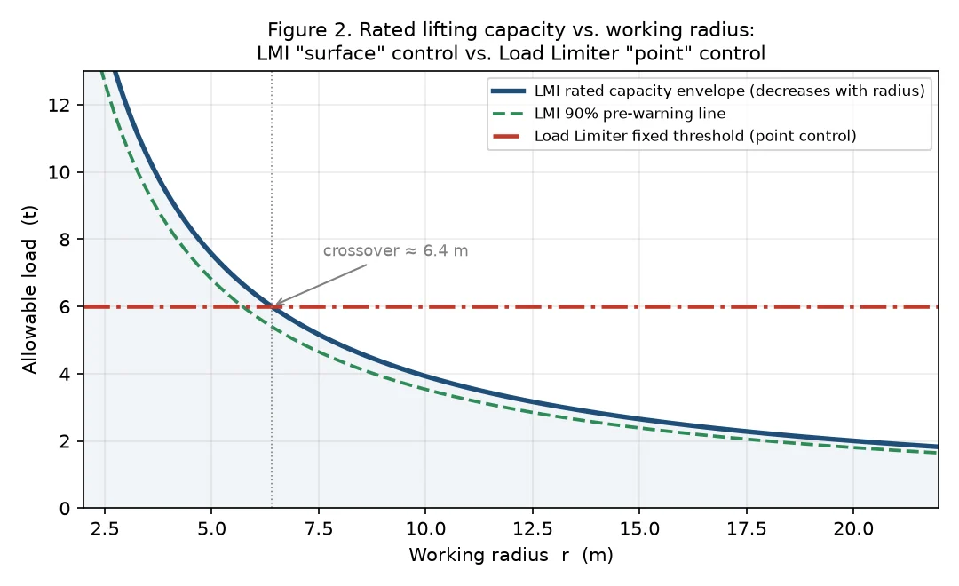
Figure 2. Capacité de levage nominale en fonction du rayon d'action : enveloppe LMI par rapport au seuil fixe du limiteur de charge. En dessous du point d'intersection (~6,4 m), c'est le limiteur qui prévaut ; au-delà, c'est le LMI qui prévaut.
3.2 Relation de couplage entre les deux
Dans la pratique, ces deux éléments n'existent pas isolément, mais sont liés et complémentaires.
Tout d'abord, la charge est la variable fondamentale pour le calcul du couple. L'algorithme d'un LMI doit intégrer le signal d'entrée provenant du capteur de charge. En cas de défaillance du limiteur de charge ou de dérive des données, les résultats de calcul du LMI seront inévitablement erronés, ce qui entraînera une défaillance du dispositif de protection.
Deuxièmement, dans certaines conditions de travail, leurs limites de contrôle diffèrent. Par exemple, au rayon minimal (longueur de flèche la plus courte), le facteur limitant pour une grue est souvent la force de traction maximale du mécanisme de levage (limiteur de charge) ; tandis qu’au rayon maximal (longueur de flèche la plus longue), le facteur limitant est la stabilité anti-basculement de l’ensemble de la machine (LMI).
Tableau 4. Dispositif de protection principal par scénario d'exploitation
| Scénario | Plage de rayon | Appareil principal | Raison |
| Flèche courte / rayon minimal | r < environ 6 à 8 m | Limiteur de charge | Enveloppe de capacité > capacité maximale du palan ; la résistance du palan constitue le goulot d'étranglement |
| Fonctionnement à moyenne portée | environ 6 à 15 m | Les deux sont actifs | L'un ou l'autre peut se déclencher en premier, selon la répartition de la charge. |
| Flèche longue / rayon maximal | r > environ 15 m | LMI | La marge de stabilité se réduit ; le risque de renversement prend le dessus |
| Conditions de vent fort | Tout rayon | LMI (version améliorée) | Le vent génère un moment de renversement ; le LMI tient compte des facteurs environnementaux |
| Levage dynamique (accélération) | Tout rayon | Les deux | Les charges dynamiques augmentent à la fois W et M effectif |
C'est pourquoi les systèmes modernes de contrôle de sécurité de pointe adoptent généralement une stratégie de « double protection » : le système surveille simultanément le poids et le moment, déclenchant un arrêt si l'un ou l'autre de ces paramètres dépasse la norme, ce qui permet de mettre en place un réseau de protection complet.
4. Domaines d'application et analyse de cas
4.1 Génie civil et construction de ponts
Dans le cadre de l'utilisation des grues à tour et des grues sur chenilles, les indicateurs de moment de charge jouent un rôle crucial. En raison de l'environnement complexe des chantiers, des perturbations dynamiques telles que les charges dues au vent et les forces d'inertie sont présentes, et des opérations de relevage de la flèche sont fréquemment nécessaires. Les indicateurs électroniques de moment de charge (LMI) peuvent ajuster la courbe de charge nominale en temps réel en fonction de la longueur et de l'angle de la flèche, empêchant ainsi les opérateurs de provoquer un renversement dû à des erreurs de manipulation lorsque la flèche est déployée à fond. Parallèlement, les limiteurs de charge empêchent les surcharges causées par le levage de matériaux denses tels que les barres d'armature et le béton.
Exemple illustratif — Projet de grue à tour en milieu urbain :
Type de projet : Immeuble résidentiel de grande hauteur (plus de 40 étages) | Équipement : Grue à tour QTZ125 (capacité nominale maximale de 8 t)
| Observation clé : lors des levages de la benne à béton à r = 18 m, le LMI a affiché un moment nominal de 87% (approchant la zone d'alerte). L'opérateur a réduit le rayon à 14 m, ce qui a ramené le rapport à 62%. Sans l'affichage du LMI, l'opérateur aurait pu continuer à déployer la flèche, au risque de renverser la machine.
| Résultat : aucune situation de surcharge n'a été constatée pendant les 18 mois qu'a duré le projet. (Les paramètres sont donnés à titre indicatif ; ils reflètent des scénarios typiques d'utilisation de grues à tour en milieu urbain, tels que décrits dans les rapports du secteur.)
4.2 Quais portuaires et entrepôts logistiques
Lors de l'utilisation des grues à portique et des grues de quai, le rythme de travail est soutenu, avec des opérations fréquentes de levage et d'abaissement d'un point à un autre. Dans ce contexte, le rôle des limiteurs de charge est d'autant plus important, car ils servent à empêcher les grappins ou les conteneurs de dépasser les limites de poids. Par ailleurs, le rayon de la flèche étant généralement fixe ou ne pouvant varier que dans une plage limitée, la limitation du moment sert principalement de protection d'appoint contre le glissement ou le renversement de l'équipement en cas de vents violents.
Exemple illustratif — Grue de quai d'un terminal à conteneurs :
Équipement : grue à conteneurs navire-terre | Opération : cycle de manutention des conteneurs (45 s en moyenne par levage)
| Observation clé : le limiteur de charge s'est déclenché 23 fois en un mois, toujours en raison de conteneurs en surcharge (dépassant la limite de 41 tonnes par EVP). Aucun déclenchement du LMI n'a été enregistré, car le fonctionnement à rayon fixe maintient le moment bien en deçà des limites autorisées. Depuis la mise en place du système de double protection : aucun incident de cisaillement de câble n'a été signalé.
| Conclusion : démontre que, lors des opérations portuaires à rayon fixe, le limiteur de charge constitue le dispositif de protection principal ; le LMI sert de dispositif secondaire de contrôle de la stabilité. (Illustration basée sur des données d'exploitation typiques d'un terminal.)
4.3 Applications dans des domaines spécifiques
Dans le domaine de l'installation d'éoliennes et de la construction de centrales nucléaires, la valeur des équipements est extrêmement élevée et les risques sont immenses. Les applications dans ces domaines nécessitent non seulement des indicateurs de moment de charge et des limiteurs de charge de haute précision, mais également des conceptions de systèmes redondants (double processeur, double capteur) et des fonctions d'enregistrement des données (boîtes noires) pour la reconstitution et l'analyse des événements après un accident.
Exemple illustratif — Navire d'installation de pales d'éoliennes en mer :
Environnement : Plateforme en pleine mer, houle importante | Équipement : Grue offshore pour charges lourdes
| Architecture de sécurité : LMI à double processeur + capteurs de charge redondants + suivi de position par GPS
| Exigence clé : calcul en temps réel du moment avec compensation du soulèvement, tenant compte du roulis et du tangage du navire
| Conformité aux normes : CEI 62786 (sécurité des grues offshore) + ISO 19901 (structures offshore)
| Résultat : la conception redondante garantit qu'un point de défaillance unique ne met pas la protection hors service. (Architecture à titre d'exemple, basée sur les meilleures pratiques du secteur de l'éolien offshore.)
5. Conclusion
Les indicateurs de moment de charge et les limiteurs de charge constituent les deux piliers de la technologie de sécurité des grues. Les indicateurs de moment de charge se concentrent sur la stabilité globale de la machine et le contrôle du moment structurel, grâce à un couplage variable multidimensionnel ; les limiteurs de charge se concentrent quant à eux sur le contrôle de la valeur absolue de la charge soulevée, grâce à une surveillance à variable unique. Bien que différents dans leur principe, ils se complètent fonctionnellement et forment ensemble la barrière de protection de sécurité des grues.
Avec le développement de l’Internet des objets (IoT) et des technologies du big data, les futurs dispositifs de limitation de sécurité ne se limiteront plus à la simple « limitation », mais évolueront vers la « prédiction » et la « gestion ». L’évaluation en temps réel de l’état de santé des équipements et l’alerte précoce des risques opérationnels grâce à l’analyse des données dans le cloud constitueront un axe de recherche important dans ce domaine. Dans la pratique de l’ingénierie, ces deux types de dispositifs doivent être configurés de manière raisonnable et étalonnés régulièrement, en stricte conformité avec les caractéristiques des équipements et les environnements d’exploitation (conformément aux normes ISO 10245, GB/T 12602 et aux réglementations nationales applicables), afin de garantir leur sensibilité et leur fiabilité, et de protéger ainsi efficacement les vies humaines et les biens.
Références
Remarque : le texte ci-dessous comprend des normes internationales et nationales vérifiées, ainsi qu'un modèle de référence bibliographique proposé. Les informations relatives aux normes sont exactes à la date de révision.
| Réf. | ID / Source | Titre / Description | Éditeur / Lieu |
| [S1] | Série ISO 10245 | Grues — Dispositifs de limitation et de signalisation | Organisation internationale de normalisation |
| [S2] | GB/T 12602 | Dispositifs de protection contre les surcharges pour grues | Administration chinoise de la normalisation |
| [S3] | EN 13000 | Grues — Grues mobiles | Comité européen de normalisation (CEN) |
| [S4] | ANSI/ASME B30.5 | Grues mobiles et grues montées sur locomotive | Société américaine des ingénieurs en mécanique |
| [S5] | OSHA 29 CFR 1926 Subpart CC | Grues et derricks dans le secteur du bâtiment | Administration américaine chargée de la sécurité et de la santé au travail |
| [S6] | GB/T 28264 | Grues — Systèmes de gestion de la surveillance de la sécurité | Administration chinoise de la normalisation |
| [S7] | IEC 62786 | Grues offshore — Exigences de sécurité | Commission électrotechnique internationale |