Раскрытие информации: Компания SeeZol производит индикаторы момента нагрузки, ограничители номинальной грузоподъемности и бортовые системы взвешивания для кранов и подъемного оборудования. Данная статья была подготовлена нашей собственной редакционной командой, а продукты, ссылки на которые приведены в заключительной части, являются нашей продукцией. Все факты, касающиеся происшествия, взяты из открытых источников и официальных текстов цитируемых стандартов; технический анализ и мнения принадлежат редакционной команде и не отражают позицию какого-либо регулирующего органа или стороны, причастной к данному происшествию.
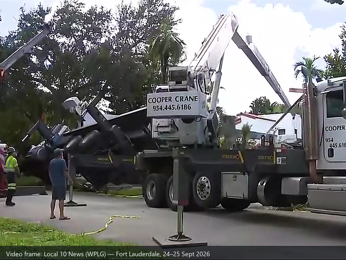
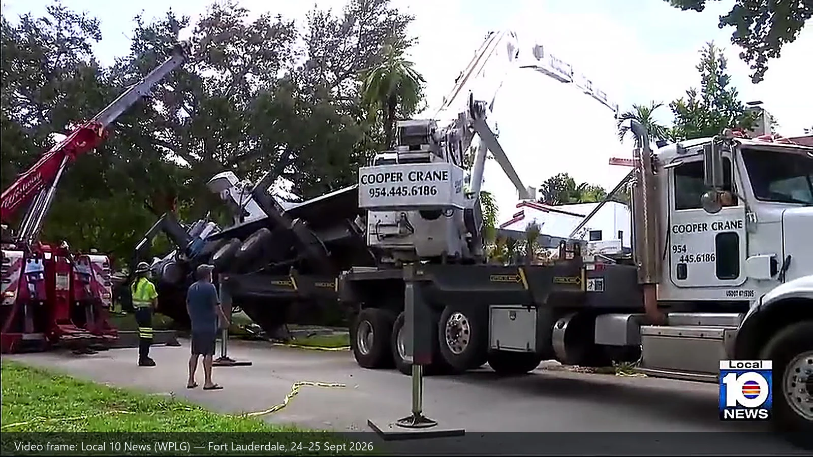
Вступление: Утром в четверг, 24 сентября 2026 года, в районе Рио-Виста города Форт-Лодердейл, штат Флорида, самосвал с краном опрокинулся на дом. Его наняли для того, чтобы поднять на крышу палатку для дезинсекции от термитов. Спустя несколько часов кран, который прибыл, чтобы снять палатку с крыши, также опрокинулся. Никто не пострадал — в доме только что завершился годовой ремонт, и внутри никого не было, — но в итоге на одной крыше оказались два крана, и причины обеих аварий по-прежнему расследуются.
Два случая выхода кранов из строя за один день — событие настолько редкое, что к нему стоит отнестись с особым вниманием по одной конкретной причине: Оба сбоя находятся по разные стороны границы зоны видимости индикатора момента нагрузки. Второй случай — полностью выдвинутая пятисекционная стрела, поднимающая груз, вес которого никто не определил, — полностью попадает в диапазон LMI. Первый случай — провал грунта под нагруженной опорой — находится за пределами этого диапазона и всегда будет за его пределами.
Именно эта граница и является темой данной статьи. Кроме того, это то, что нашей отрасли сложнее всего объяснить, поскольку честное описание этой границы выглядит для аппаратного обеспечения менее выгодно, чем рекламная версия.
1. Что произошло, в хронологическом порядке
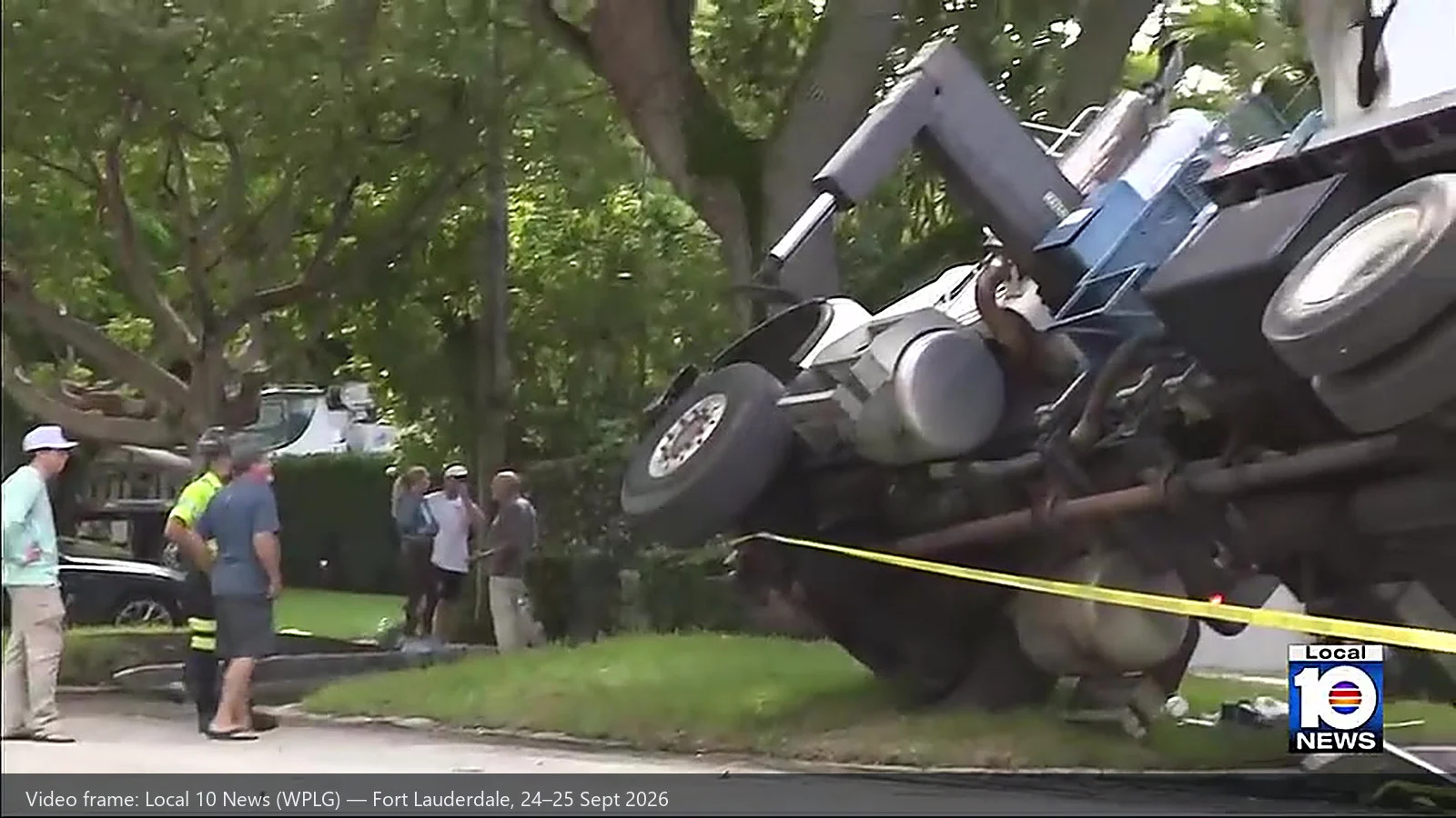
Составлено на основе материалов CBS News Miami, WPLG Local 10, NBC 6 South Florida и специализированного издания в сфере подъемной техники Vertikal.net:
| Пункт | Как сообщалось |
|---|---|
| Дата / время | Четверг, 24 сентября 2026 года. Служба пожарной охраны и спасения Форт-Лодердейла получила первый звонок по номеру 911 примерно в 09:15. |
| Местоположение | Юго-восточная 8-я улица, район Рио-Виста, Форт-Лодердейл, округ Бровард, штат Флорида. Как сообщает телеканал WPLG Local 10, 700-й квартал; Канал NBC 6 со ссылкой на пожарно-спасательную службу Форт-Лодердейла сообщает, что 800-й квартал. Эти две версии расходятся, и в данной статье приводятся обе. |
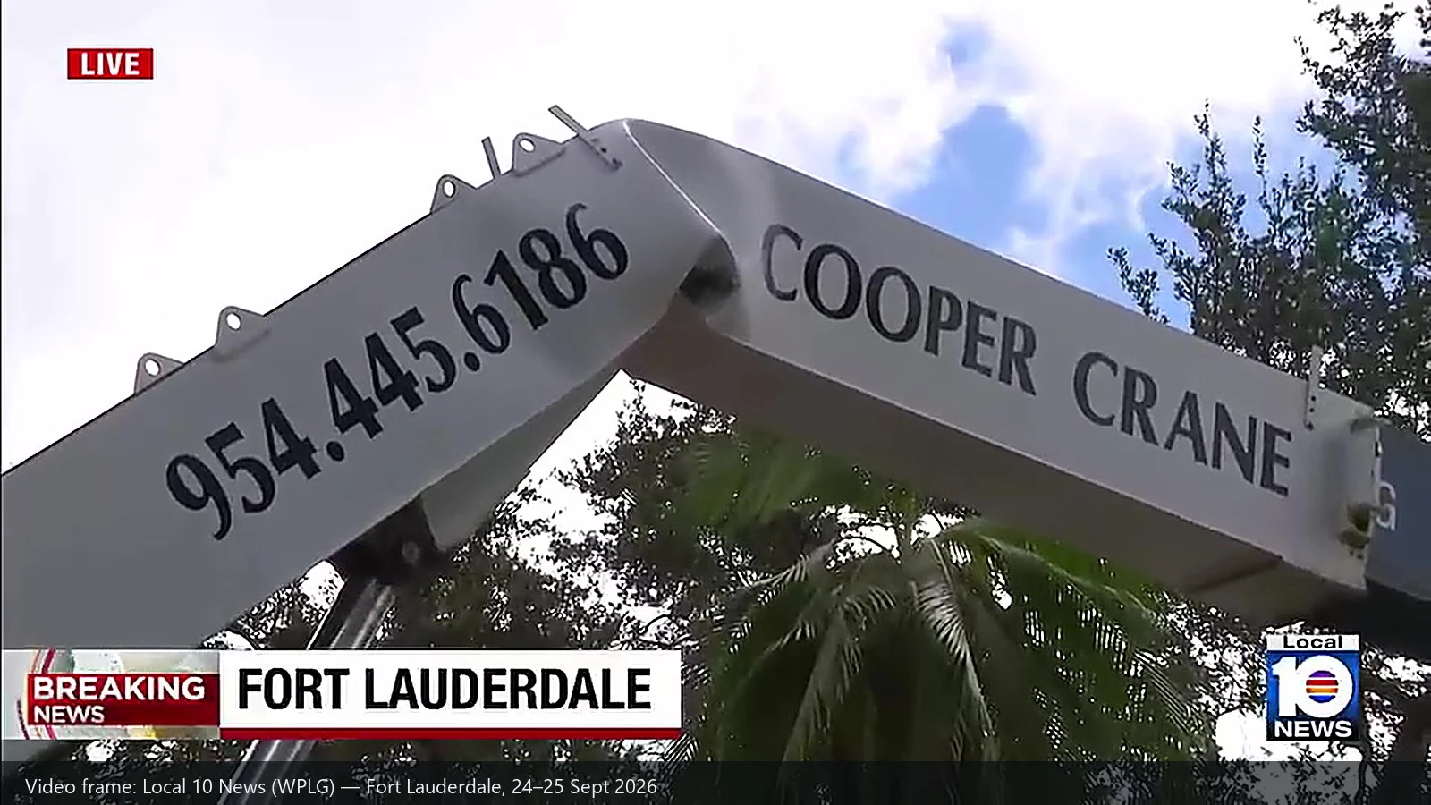
| Оборудование | Автокран (телескопический кран, установленный на грузовике), принадлежащий компании «Cooper Crane», расположенной в Вест-Парке, штат Флорида. Вторая машина была описана как автокран большего размера. |
| Задача | Подрядчик по дезинсекции использовал кран для установки над крышей палатки для фумигации в целях борьбы с термитами — это обычная работа в Южной Флориде. |
| Ошибка 1 | Передняя опора со стороны груза не выдержала нагрузки — возможно, провалившись в пустоту — и грузовик перевернулся. В сообщениях указывалось, что стабилизирующие опоры были вырваны из земли. Стрела обрушилась на крышу и заднюю стенку. |
| Ошибка 2 | Через несколько часов, когда второй, более крупный кран поднимал первый кран, чтобы убрать его, секция основания стрелы этого крана погнулась. Пятисекционная стрела спасательного крана была полностью выдвинута, и подъем осуществлялся с помощью одного троса, закреплённого на стропе, закреплённой на середине стрелы упавшего крана. |
| Травмы | Никого. Дом был пуст; владельцы только что завершили длившийся год ремонт. |
| Ответ | Бригада по ликвидации аварий с опасными веществами, вызванная в связи с утечкой дизельного топлива; инспектор пожарной охраны и городской строительный инспектор; здание было признано небезопасным; на месте происшествия находились инспекторы OSHA, которые беседовали с рабочими. |
| Далее | Работы по ликвидации последствий продолжались до пятницы, 25 сентября: бригады собрали разлитую гидравлическую жидкость и привлекли большой грузовик для демонтажа и вывоза поврежденного оборудования (WPLG Local 10). Компания Cooper Crane привлекла команду специалистов для демонтажа стрел. Компания заявила, что сотрудничает с владельцем объекта, властями и своей страховой компанией, и что не может комментировать детали, пока ведётся расследование. |
Комментарий одного из соседей, процитированный CBS News Miami, сразу же затрагивает суть вопроса: «Если посмотреть на то, как были устроены фундаменты, то видно, что там не использовали опорную площадку, которая была бы достаточно большой, чтобы распределить нагрузку, да и сама нагрузка была не такой уж большой». Оправдается ли это предположение — покажет расследование.
2. Что на самом деле измеряет индикатор нагрузочного момента
Прежде чем рассмотреть эти два сбоя с разных точек зрения, стоит более точно определить, что представляет собой сам прибор. Индикатор момента нагрузки не «обнаруживает перегрузку» в абстрактном смысле. Он непрерывно выполняет один расчет на основе измеренных входных данных.
Нагрузка × радиус = момент нагрузки. Система сравнивает этот рассчитанный момент с номинальным значением для той конфигурации, в которой, согласно заданным данным, она находится, и принимает меры, когда эти два значения сближаются. Все остальное в системе LMI сводится к этим трём этапам: измерение, расчёт, сравнение — а затем выдача предупреждения или остановка.
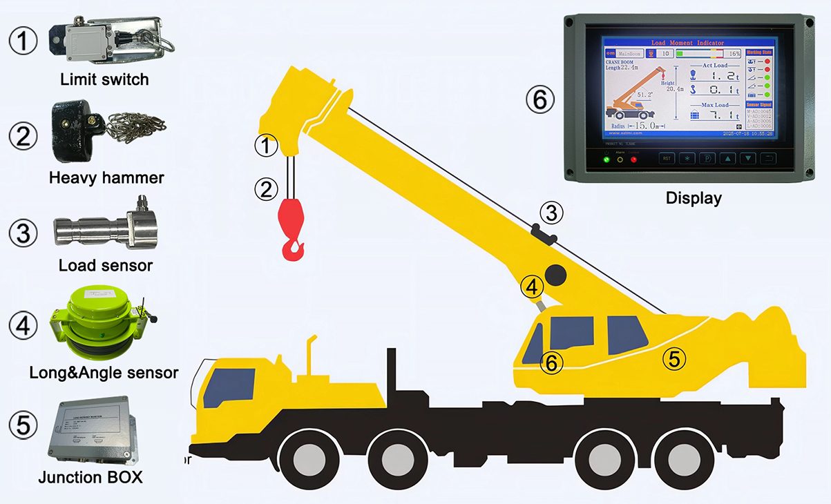
| What gets measured | With what | What it becomes |
|---|---|---|
| Force in the hoist line / at the hook block | Load sensor (load cell) in the running rope or at the dead end | Actual load — displayed directly in tonnes or pounds |
| Pressure in the luffing or hoist hydraulic circuit | Hydraulic pressure transducer | An indirect route to actual load, where a load cell is not fitted |
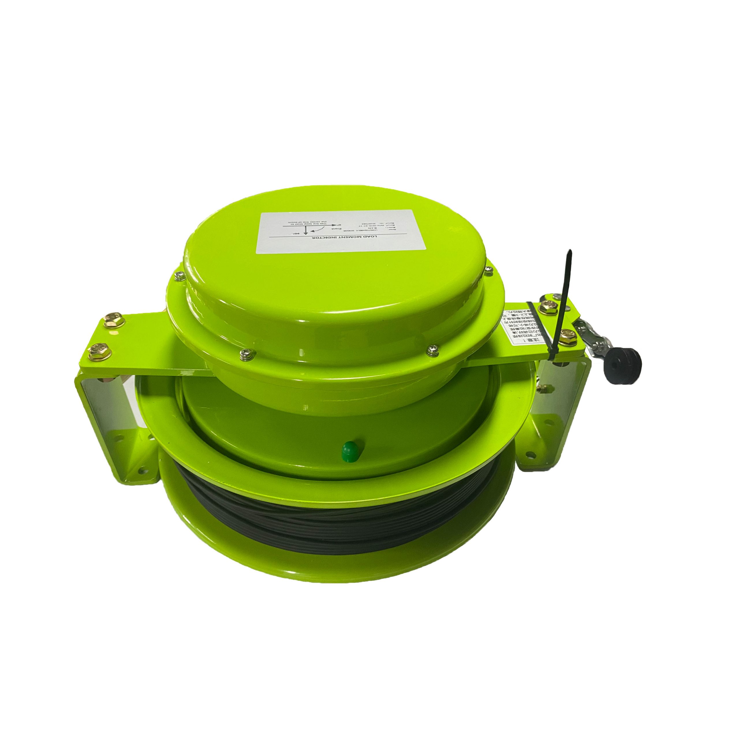
| Длина штанги | Length sensor on the cable reel or a draw-wire encoder on the boom | Radius, together with angle |
| Угол наклона стрелы | Angle sensor on the boom root or a pendulum | Radius and head height |
| Computed load moment | Derived from the above | Percentage of rated capacity — the number the alarm and cut-out act on |
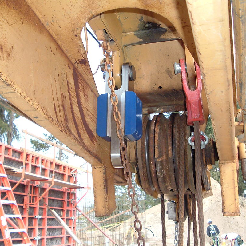
What that architecture buys, in practice, is a specific set of functions — and it is worth listing them plainly, because they define the boundary:
- Live display of actual load, radius, boom length, angle and percentage of rated capacity. Not a warning light, but a number the operator can watch close in.
- Two-stage alerting and cut-out. A pre-warning band, and a limit at which the system takes over — typically by stopping the motions that increase moment: hoist up, telescope out, luff down.
- Configuration management. The rated values come from the configuration the system is told it is in: boom combination, jib or fly, counterweight, and whether the outriggers are fully or partially extended. A machine on outriggers and the same machine on tyres have different charts.
- Event recording, and on newer systems telematics. Load cycles, peak values and alarm or override events, logged rather than lost. This is the function that turns a machine into a data source after an incident, instead of a machine that has to be reconstructed from bystander video.
Every one of those functions depends on four assumptions, and it is these that decide where the line falls: that the machine is level, that the outriggers are carrying load as assumed, that the configuration entered matches the configuration in use, and that the system has not been bypassed.
3. Failure two: the failure a load moment indicator was built for
An overturned crane looks like a known quantity. It has a documented mass, and its owner knows exactly which model it is. That is the trap. The number that matters to the recovery crane is not the fallen machine’s gross weight — it is the force required to break it free and hold it. That force is assembled from things nobody can read off a nameplate: soil suction and embedment, structural interference from the building it is leaning on, sling geometry, and the fact that a release can be sudden enough to convert a static load into a dynamic one.
Against all four of those unknowns, an LMI offers exactly one thing — and in this scenario it is the thing that matters. It can weigh the load while the load is barely off the ground.
US regulation does not merely permit that method; it makes it one of two legal routes. §1926.1417(o)(3) requires the operator to verify that a load is within rated capacity either by determining the weight from an industry-recognised source or calculation method before the lift, или by beginning to hoist and using a load weighing device, Индикатор момента oad, rated capacity indicator or rated capacity limiter to establish whether the load exceeds 75 percent of the maximum rated capacity at the longest radius that will be used. If it does, the lift must stop until the weight has been established properly.
— OSHA 29 CFR 1926.1417(k)
Read the two provisions together and the operating instruction for a recovery lift writes itself. The instrument gives you the weight on a three-inch pick; the regulation gives you the threshold at which to stand down. What the setup needs in addition is three things that no instrument supplies: an LMI configured for the boom and rigging actually in use (five sections out, single line, sling at mid-boom is not the configuration the display was showing last week), someone with the authority to abort at that moment, and a unit capable of producing a reading worth trusting in the first place — the difference is set out in our comparison of onboard weighing vs load indicator vs load scale.
4. Failure one: the half of the lift no load moment indicator is watching
Now the other side of the line. A load moment indicator sits above the outrigger jack. That single sentence explains the first failure completely.
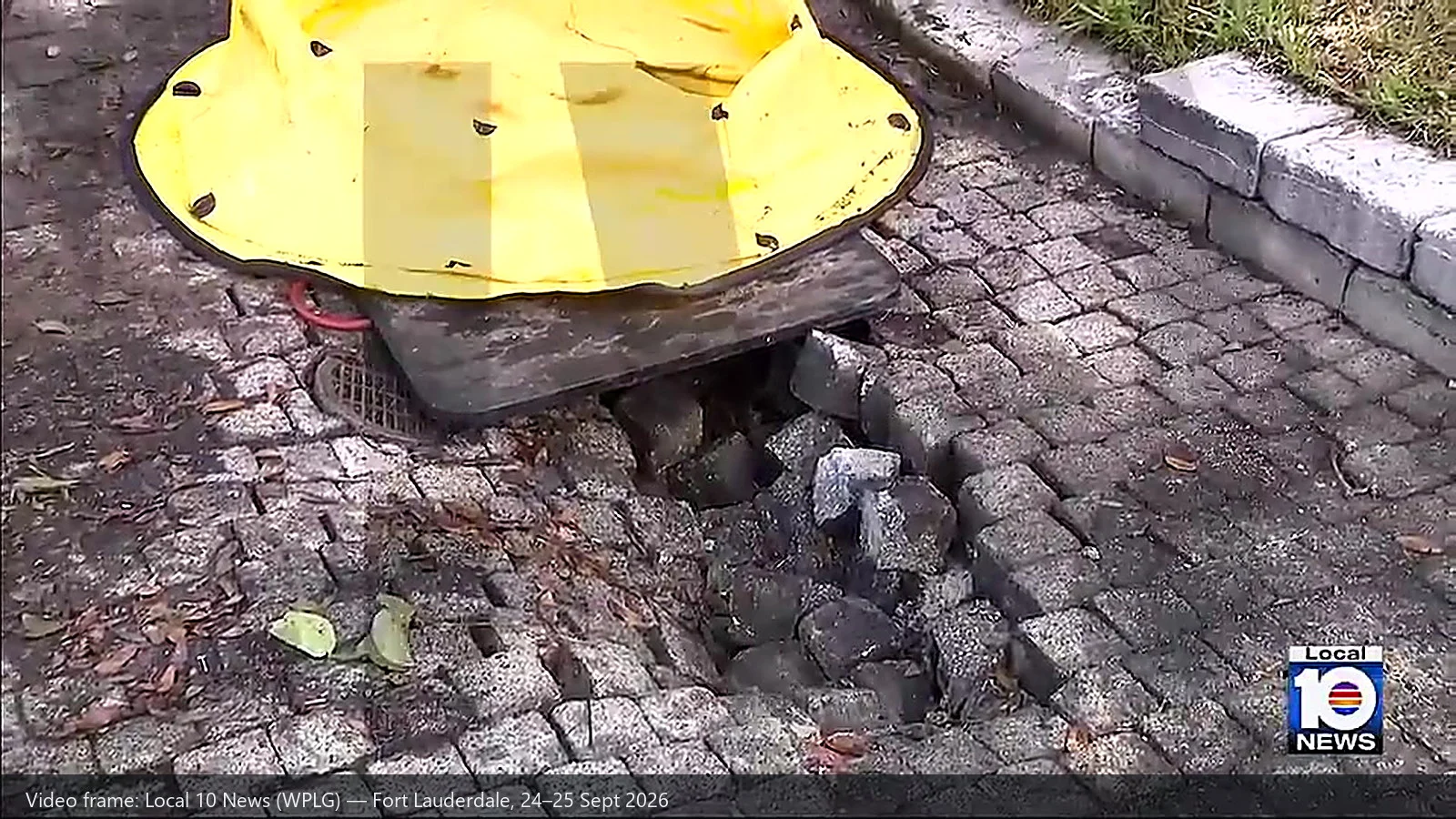
A load chart is not a property of the crane alone. Every rated capacity printed on it rests on three assumptions: that the machine is level, that the outriggers are fully deployed as specified, and that the ground under each float or pad will carry the reaction it receives. Only the first two are instrument-monitored. If a pad sinks three inches into fill that was never compacted, the instruments on the machine will report a perfectly normal lift while the machine is already going over. The measurement chain shown above simply does not extend below the jack.
There is a second-order point here that is easy to miss, and it connects the two failures. The outrigger reaction is derived from the same geometry the LMI uses. The reaction on each pad is a function of load, radius, machine mass and configuration — which is to say, of the load moment. The data exists in the same load chart, and the calculation is not exotic. What the LMI cannot do is verify the assumption underneath it: that the surface receiving that reaction is still there.
US regulation puts the burden where an instrument cannot. OSHA 29 CFR 1926.1402 Ground conditions requires that equipment not be assembled or used unless ground conditions are “firm, drained, and graded to a sufficient extent so that, in conjunction (if necessary) with the use of supporting materials, the equipment manufacturer’s specifications for adequate support and degree of level of the equipment are met.” That same section requires the controlling entity to:
— OSHA 29 CFR 1926.1402(c)(2)
In residential work, the classic void is invisible: a septic tank, a disused cistern, a drainage culvert, a utility trench backfilled a decade ago. The visible surface gives no warning. On top of that, §1926.1415(a)(5) requires hydraulic outrigger jacks to have an integral holding device or check valve — a rule that addresses sudden loss of jack pressure, not the ground beneath the pad. Where jack pressure can be monitored, a hydraulic pressure sensor is the closest link in the chain to whether the outrigger is still carrying — but it reports pressure in the cylinder, not bearing capacity in the soil.
One more thing worth confirming: this rule set does cover the machine in question. OSHA 29 CFR 1926.1400(a) lists “wheel-mounted, rough-terrain, all-terrain, commercial truck-mounted, and boom truck cranes” among the equipment within scope. The landing points differ by market, though — for how equivalent requirements read in the EU, China and elsewhere, see our comparison of 2026 global crane safety standards (EU / US / China).
5. The line, drawn: what an LMI catches and what it does not
This is where vendors, including us, should be careful. An LMI is a load and geometry instrument. It is very good at its own job and structurally incapable of a neighbouring one. The table below is the honest version.
| Failure mode in this case | Can an LMI / RCL catch it? | What actually prevents it |
|---|---|---|
| Overload / over-moment at long radius — five sections out, single line | Да — if configured for the actual boom and rigging, calibrated, and not bypassed | Configured LMI/RCL with pre-warning and cut-out, plus load chart discipline |
| Lifting a load whose weight nobody established | Yes, as the measuring instrument — the system reads the weight during a test pick-up, and §1926.1417(o)(3)(ii) names it as an accepted route | A pre-lift estimate where possible, plus a documented stop threshold and someone empowered to use it |
| Wrong configuration entered — boom combination, counterweight, outrigger state | Нет. The system compares against the chart it was given, faithfully and obediently | Pre-lift configuration check, and systems that log configuration changes |
| Ground bearing failure — pad punching into a void | Нет. The instrument sits above the jack; the measurement chain stops at the cylinder | Ground assessment, pad sizing from outrigger reaction, site information flow, a spotter watching the pads |
| Side loading, boom contact with an obstruction | Нет. These are rigging and planning errors, not load errors | Lift plan, rigging supervision, correct sling geometry |
| An instrument that is bypassed, uncalibrated or unserviceable | Not by itself — a defeated device reports nothing useful | §1926.1415(b): a device not in proper working order puts the equipment out of service; no workaround is permitted |
For the abbreviations used above and the standards behind each one, see LMI / SLI / RCI / RCL explained with standards and specifications; for what the sensors themselves can and cannot resolve, see the key numerical indicators of LMI core sensors.
The pattern is consistent, and it is the one sentence worth taking away: instrumentation protects the machine from its load; people protect the machine from its setup. A correctly configured LMI will not let a boom exceed its rated moment for the configuration it is in — and it will keep reporting normal values all the way to the ground if the machine is standing on ground that is no longer there.
6. An eight-point LMI specification checklist for fleets and OEMs
Read as a purchasing and configuration checklist rather than an incident post-mortem, the same case produces eight questions. The first six are about the instrument; the last two are about the people and the record around it.
| # | Question | Why this case makes it concrete |
|---|---|---|
| 1 | Does the system take its load signal from a true load sensor on the running rope, or infer it from hydraulic pressure? | An inferred signal is adequate for overload protection but weaker for the test-pick weighing that §1926.1417(o)(3)(ii) relies on. |
| 2 | Are boom length and angle measured directly, and is radius computed from them? | The percentage of rated capacity on the display is only as good as the geometry feeding it. |
| 3 | Does the configuration menu cover every state the machine actually works in — boom combinations, jib, counterweight variants, outrigger fully / partially extended, on tyres? | A chart for the wrong configuration is worse than no display, because it is trusted. |
| 4 | Does the cut-out act on the motions that increase moment — hoist up, telescope out, luff down — rather than only raising an alarm? | A warning the operator must act on is a warning that can be missed at the moment it matters. |
| 5 | Are cut-out and override events logged, with time stamps, and are configuration changes logged too? | It converts an incident from “reconstructed from bystander video” into a readable record. |
| 6 | Is calibration a scheduled item, and are the known drift and installation pitfalls understood by the people doing it? | See the five common calibration pitfalls. |
| 7 | Is the recovery of a fallen machine classified as a critical lift, with load verification, a written plan and a competent person on site? | It is the highest-variance lift most fleets ever attempt. |
| 8 | For soft or unknown ground, is there a pad-sizing procedure based on the chart’s outrigger reaction data — and a way to confirm what is under the pad? | The one part of the lift the instrument cannot verify. |
Questions 3 and 5 are the two that most often separate a compliant installation from a merely present one. Configuration comes down to the key parameter checklist for LMI selection; logging and remote visibility are what the shift from single-chip controllers to IoT edge computing has made practical, and they are exactly what a scene like this one lacks. For a fleet-level view of what an upgrade is worth, see why an LMI is the smartest upgrade for a truck crane, and for the distinction that trips up a lot of tenders, LMI vs load limiters.
How SeeZol fits in
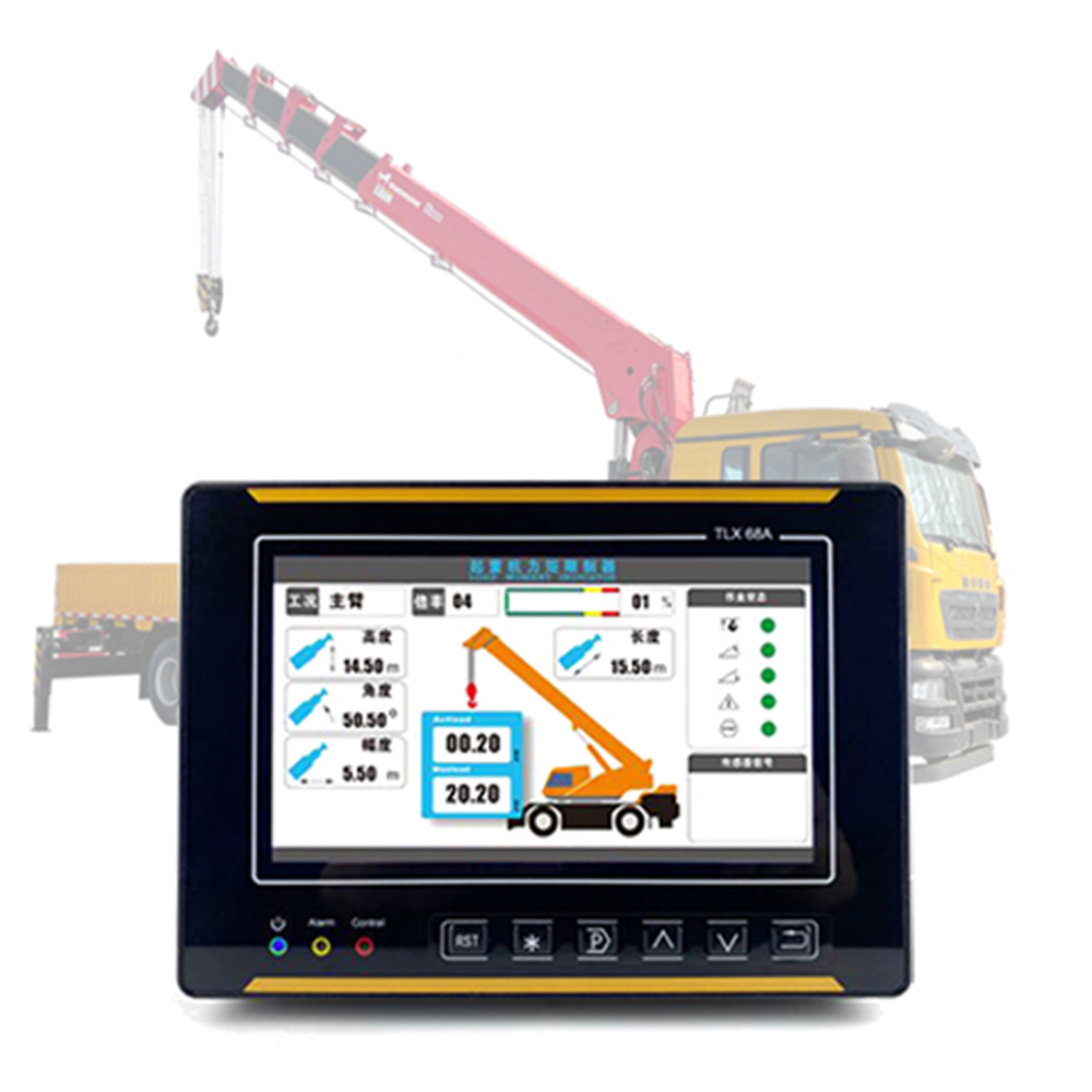
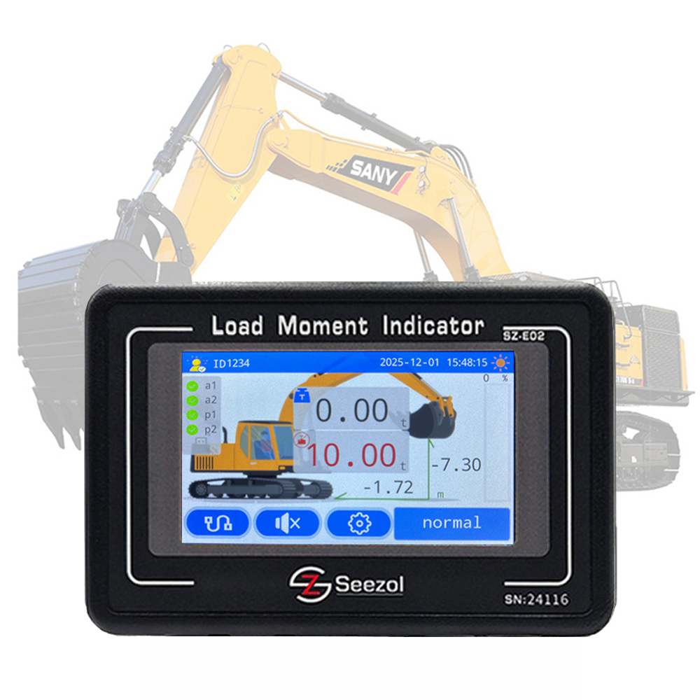
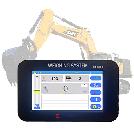
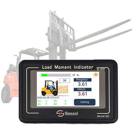
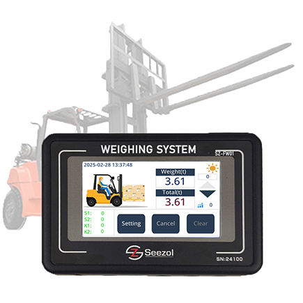
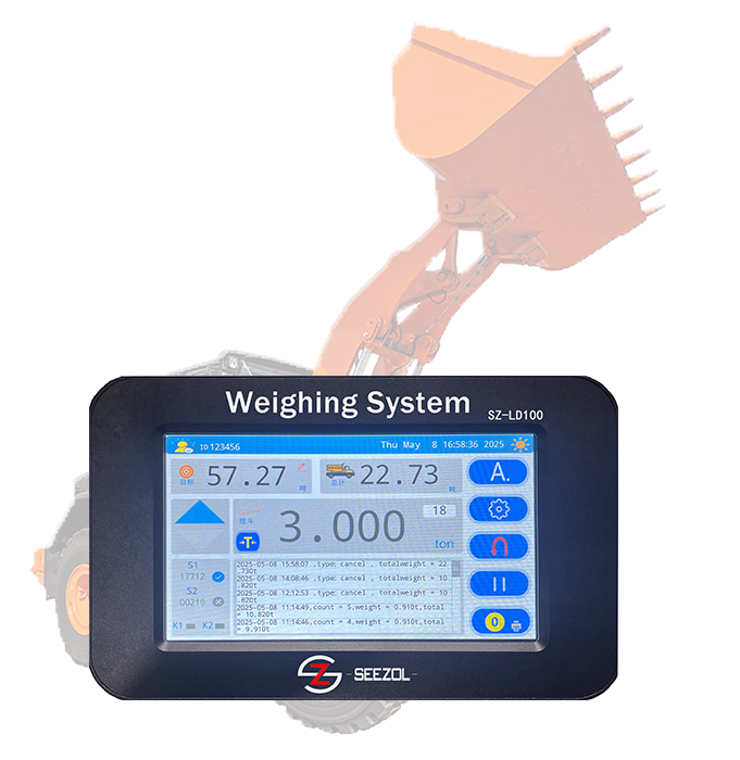
SeeZol builds load moment indicators, rated capacity limiters and onboard weighing systems for truck cranes, articulated boom cranes, crawler cranes, marine cranes and material handlers. A typical system pairs a load sensor on the running rope, a length and angle sensor on the boom, a junction box and a cab display that shows actual load, radius, boom length, angle and percentage of rated capacity, with pre-warning, cut-out and event logging. Systems can also be specified with hydraulic pressure sensing where a load cell cannot be fitted, with onboard weighing for machines that need to record what they carried, and with telematics where a fleet needs the data off the machine.
Start from the product pages: Мобильный кран LMI, Кран с шарнирно-сочлененной стрелой LMI, crane safe load limiter, hydraulic pressure sensor — or send us your machine model and boom configuration and our engineers will come back with a proposed sensor chain and configuration list, usually within 24 hours.
Sources
- Vertikal.net, Twin crane failure, 2026-09-25 (includes CBS affiliate video of the second failure) — link
- CBS News Miami, Crews work Friday to remove 2 cranes that collapsed on Fort Lauderdale roof, as neighbors question what happened - link
- CBS News Miami, Video shows second crane collapsing onto roof of Fort Lauderdale home; no injuries reported - link
- WPLG Local 10, Crane falls onto Fort Lauderdale house after boom truck tips over, 2026-09-24 (source of the incident images) — link
- WPLG Local 10, Cleanup continues after 2 cranes topple in Fort Lauderdale neighborhood; company responds, 2026-09-25 (Cooper Crane statement, OSHA involvement; source of the incident images) — link
- NBC 6 South Florida, 2nd crane topples onto home in Fort Lauderdale while trying to remove 1st - link
- OSHA, 29 CFR 1926.1400 Scope — confirming that boom trucks fall under Subpart CC — link
- OSHA, 29 CFR 1926.1402 Ground conditions - link
- OSHA, 29 CFR 1926.1415 Safety devices - link
- OSHA, 29 CFR 1926.1417 Operation - link
- SeeZol, technical: LMI / SLI / RCI / RCL explained, key numerical indicators of core sensors, LMI selection parameter checklist, LMI principles and composition, onboard weighing vs load indicator vs load scale, core sensor analysis
- SeeZol, compliance and applications: Why a load moment indicator is the smartest upgrade for your truck crane; 5 common LMI calibration pitfalls; LMI vs load limiters; EU crane safety compliance in 2026; how to choose an LMI for your machine