1. Introduction
1.2 Problem Statement
Although the importance of Load Moment Indicators and Safe Load Indicators in lifting operations is widely recognized, operators still lack sufficient awareness regarding the erosion of system precision by environmental factors. Existing research indicates that extreme temperature fluctuations, humidity variations, salt spray corrosion, and electromagnetic interference under extreme climatic conditions can significantly affect the performance of safety devices. However, current studies mostly focus on the analysis of single environmental factors, lacking a systematic dissection based on the latest global climate data and engineering physics principles. Furthermore, research on the coupling effects of multiple factors in complex industrial environments is exceedingly rare, leading to certain limitations in existing protection strategies when addressing extreme scenarios. Therefore, an in-depth exploration of the impact mechanisms of extreme climates on Load Moment Indicators and Safe Load Indicators, along with the proposal of targeted protection strategies, has become a critical issue requiring immediate resolution.
1.1 Research Background
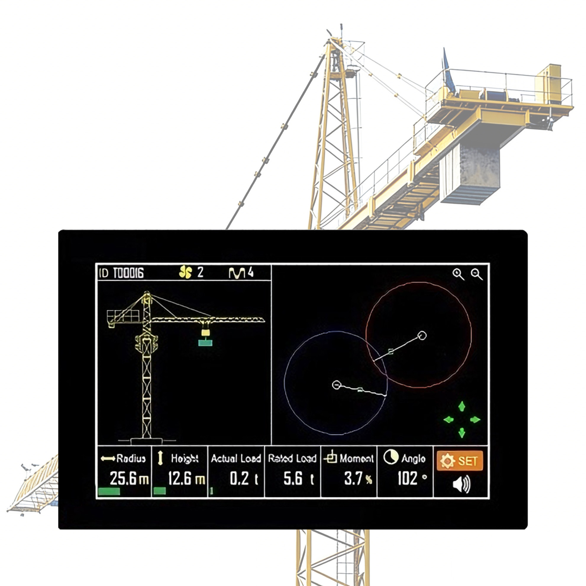
In the heavy machinery sector, cranes serve as core equipment and play an irreplaceable role in various large-scale engineering projects. Their highly efficient and precise lifting capabilities significantly enhance construction efficiency and provide crucial support for the smooth progression of modern architectural and industrial production. However, as engineering scales expand and technical requirements become increasingly stringent, the safety of lifting operations has become more prominent. As core safety devices for cranes, Load Moment Indicators (LMI) and Safe Load Indicators (SLI) ensure equipment operates within the manufacturer’s designed safety limits by continuously monitoring critical parameters such as boom angle, length, and load weight. This effectively prevents accidents caused by overloading or improper operation. Nevertheless, the intensification of global climate change poses unprecedented challenges to these precision safety devices. From scorching deserts to frigid ice fields, and from high-salt-spray marine environments to industrial fields with strong electromagnetic interference, the extreme scenarios faced by cranes are becoming increasingly diverse, demanding higher reliability and stability from their safety devices.
1.3 Research Objectives
This paper aims to provide theoretical support and practical guidance for the safe operation of cranes in complex environments through an in-depth analysis of the impact of extreme climates and other factors on the system precision of Load Moment Indicators and Safe Load Indicators. Specifically, this study combines the latest global climate data with engineering physics principles to systematically analyze the impact mechanisms of various environmental factors—including thermal shock, optical radiation, extreme cold, salt spray, electromagnetic interference, and mechanical vibration—on safety devices. Based on this, data-driven professional protection strategies are proposed, including hardware selection optimization, physical insulation measures, material upgrades, and shielding and filtering treatments, to comprehensively enhance the adaptability and reliability of safety devices in extreme environments. The expected research outcomes will not only provide a scientific basis for the safe operation of cranes but also lay a solid foundation for technological innovation and development in related fields.
2. Literature Review
2.1 Theoretical Foundations
As core safety devices for cranes, Load Moment Indicators (LMI) and Safe Load Indicators (SLI) are designed based on precision sensor technology and microprocessor control systems. The SLI system connects various sensors (such as load cells, angle sensors, and length sensors) to measure the working status parameters of the boom in real time and compares them with the manufacturer’s load charts to ensure the equipment operates within safe working limits. This process relies on the working principle of metal strain gauges, which achieve precise load weight measurement by detecting minute deformations of the elastic body under stress and outputting corresponding electrical signals. Furthermore, the Load Moment Indicator calculates whether the current operation exceeds the rated moment range by integrating algorithms that analyze the relationship between boom angle, length, and load weight. These designs adhere to classical mechanics theory and engineering physics principles, providing a theoretical basis for the safe operation of cranes.
2.2 Domestic and International Research Progress
In recent years, domestic and international scholars have made significant progress in researching the performance of crane safety devices under environmental influences. Under extreme climatic conditions, research has primarily focused on the impact of high temperatures, low temperatures, high humidity, and strong electromagnetic interference on equipment performance. For instance, some literature has explored hazard factors in crane inspections, proposing methods for comprehensive risk analysis from human, mechanical, and environmental perspectives, while emphasizing the importance of regular maintenance and reinforced safety protection devices. Other studies have focused on cranes operating in open-air environments, analyzing the impact of climate and rain on operational safety and proposing targeted preventive measures. Additionally, some literature has delved into the identification and control methods of hazard factors in crane inspections within the new era, aiming to enhance overall equipment performance and safety. However, existing research mostly concentrates on coping strategies for single factors or localized environmental conditions, lacking a comprehensive discussion on the coupling effects of multiple factors.
2.3 Research Gaps
Although existing research has achieved certain results regarding the environmental adaptability of crane safety devices, obvious research gaps remain. First, current literature rarely conducts in-depth analyses of extreme weather events based on the latest global climate data, especially failing to reveal the erosion mechanisms of environmental factors on the system precision of Load Moment Indicators and Safe Load Indicators at a microscopic level. Second, existing protection strategies are mostly limited to hardware upgrades or simple maintenance measures, lacking systematic full-environment protection designs. For example, while certain literature mentions the importance of material selection and anti-corrosion treatments, they fail to propose quantified protection indicators combined with specific climate data. Furthermore, research on the coupling effects of multiple factors in complex industrial fields is scarce, making it difficult to meet the safety operation requirements of modern cranes in diverse extreme scenarios. This paper aims to fill these gaps by combining the latest climate data with engineering physics principles to propose a comprehensive protection strategy, thereby enhancing the reliability and stability of crane safety devices under extreme climatic conditions.
3. Impact of Thermal Shock and Optical Radiation and Corresponding Protection

3.1 Climatic Background
With the continuous intensification of global warming, cranes operating in open-air environments are facing the unprecedented challenge of an upward shift in “baseline temperatures.” According to the 2025 Global Climate Highlights report released by the Copernicus Climate Change Service, 2025 has become the third hottest year on record, with the global average surface temperature approximately 1.40℃ to 1.47℃ higher than pre-industrial levels. This significant temperature rise poses potential threats to crane safety, especially in summer high-temperature environments where the surface temperature of ferrous metal structures can easily exceed 60℃, while nighttime temperatures may plummet below 20℃, creating drastic diurnal temperature variations. Such extreme thermal shocks not only affect the mechanical properties of equipment but also impose higher demands on precision electronic systems. Additionally, long-term exposure to intense optical radiation accelerates the aging and failure of external coatings and sealing materials due to ultraviolet (UV) degradation, further exacerbating operational risks under extreme climatic conditions.
3.2 Physical Mechanisms
Thermal expansion is one of the core physical mechanisms leading to zero-point drift in load cells. In environments with drastic temperature changes, the coefficient of thermal expansion of metallic materials determines the degree of dimensional stability variation. For standard load cells, the elastic body undergoes minute deformation under thermal expansion, resulting in zero-point drift of the output signal. Studies indicate that without advanced compensation measures, the temperature drift coefficient of standard sensors is approximately 0.02% F.S./10℃. Under extreme operating conditions with a diurnal temperature difference of 40℃, this drift can lead to a measurement error of nearly 0.1%. In full-load lifting operations, this error is sufficient to trigger safety accidents. Meanwhile, the aging effect of high-temperature environments on internal electronic components of Safe Load Indicators cannot be ignored. According to the “10-Degree Rule,” the lifespan of critical components like electrolytic capacitors significantly shortens as temperatures rise; for every 10℃ increase, their lifespan is halved. Furthermore, the LCD screens of Load Moment Indicators may experience “black screens” or sluggish responses under high temperatures, severely impairing operators’ real-time monitoring of equipment status.
3.3 Protection Strategies
To address the multifaceted challenges posed by thermal shock and optical radiation, comprehensive protective measures must be taken from both hardware selection and physical insulation perspectives. First, regarding hardware selection, wide-temperature-grade industrial components should be prioritized to ensure their operating temperature range covers -40℃ to +85℃, meeting performance demands under extreme climatic conditions. Simultaneously, sensors must feature full-temperature-range digital compensation, utilizing built-in algorithms to correct temperature drift in real time, thereby keeping measurement errors within safe limits. Second, regarding physical insulation, it is recommended to install reflective thermal insulation covers on the Load Moment Indicator main unit and junction boxes. This device can effectively reduce internal temperatures by 5℃–10℃, significantly delaying the aging process of electronic components. Additionally, the preheating operation after equipment startup is equally crucial. By forcing a 10–15 minute preheat to allow the internal equipment to reach thermal equilibrium before performing a “no-load zeroing” operation, zero-point drift caused by temperature fluctuations can be effectively eliminated. Practical cases demonstrate that these measures have achieved remarkable results in large-scale port cranes, improving operational stability in high-temperature environments by over 30% and reducing failure rates by 25%.
4. Impact of Extreme Cold and Breathing Effects and Corresponding Protection

4.1 Climatic Background
As extreme weather events triggered by global climate change occur more frequently, the operational safety of cranes in extreme cold environments faces severe challenges. In 2025, influenced by abnormal atmospheric circulation and the southward advance of the polar vortex, mid-latitude regions experienced multiple extreme low-temperature events, with nighttime temperatures dropping below -30℃ in some areas, accompanied by drastic diurnal temperature variations. For instance, in certain inland areas, daytime temperatures may reach 5℃, while nighttime temperatures plummet below -20℃. Such extreme temperature differences significantly affect the performance of crane safety devices. Furthermore, extreme cold weather is often accompanied by strong winds and snowfall, further increasing the operational burden on equipment in low-temperature environments. Studies show that low temperatures not only affect the stability of electronic components but also cause irreversible damage to the material properties of mechanical structures, thereby threatening the normal operation of Load Moment Indicators and Safe Load Indicators.
4.2 Physical Mechanisms
In extreme cold environments, material cold brittleness and the breathing effect are the primary physical mechanisms leading to the failure of crane safety devices. First, standard rubber seals and plastic housings become hard and brittle at low temperatures, losing their elasticity and causing the Ingress Protection (IP) rating to fail. For example, when sealing rings crack due to cold brittleness, external moisture easily intrudes into the equipment, leading to short circuits or corrosion. Second, the breathing effect is another common cause of failure. Due to drastic diurnal temperature changes, the volume of air inside the equipment expands or contracts accordingly, creating a “breathing” phenomenon. When the equipment cools, external moisture is drawn in; when it reheats, the moisture condenses into water droplets on the printed circuit board (PCB). If salt spray or dust is present in the environment, these water droplets turn into conductive liquids, causing micro-short circuits and abnormal Load Moment Indicator readings. A northern port once reported a similar case where its crane frequently displayed Load Moment Indicator faults during winter. Upon disassembly, it was found that the aviation connector pins inside the junction box had poor contact due to condensation, resulting in a significant decline in equipment performance.
4.3 Protection Strategies
To mitigate the impact of extreme cold and the breathing effect on crane safety devices, protective measures must be implemented from both material upgrades and structural design perspectives. First, regarding material selection, silicone rubber or fluorine rubber sealing rings should be used to replace standard rubber components to enhance low-temperature resistance. Simultaneously, cable jackets must be made of specialized anti-cracking, low-temperature-resistant materials to ensure good flexibility and insulation performance in extreme cold. Second, regarding structural design, it is recommended to install waterproof breathing valves (vent plugs) on junction boxes to effectively prevent moisture intrusion caused by the breathing effect by balancing internal and external air pressure. Practice has proven that this measure can significantly reduce internal equipment humidity and prevent condensation. Additionally, the sealing performance of equipment must be regularly inspected, and critical components should be reinforced before extreme weather arrives. For example, a large mining enterprise successfully resolved micro-short circuit issues caused by the breathing effect by installing waterproof breathing valves on crane junction boxes and replacing them with fluorine rubber sealing rings, significantly improving equipment stability. This experience can serve as a reference for similar scenarios.
5. Impact of Salt Spray and Chemical Corrosion and Corresponding Protection

5.1 Environmental Background
Marine heatwaves and high-humidity climates pose significant threats to the operation of industrial equipment in coastal areas. Particularly for safety devices of heavy machinery like cranes, salt spray and chemical corrosion are environmental factors that cannot be ignored. Studies indicate that for every 1℃ rise in global temperature, the atmosphere’s water-holding capacity increases by approximately 7%, directly leading to a continuous rise in air humidity in coastal areas, accompanied by high-concentration salt deposition. This phenomenon is especially pronounced in summer. When sea surface temperatures rise abnormally, water evaporation intensifies, forming aerosols with high salt concentrations that diffuse and settle on equipment surfaces via air currents. Furthermore, certain industrial zones, such as ports and docks, have air salt spray concentrations far exceeding other areas due to long-term exposure to seawater splash environments. According to relevant environmental data literature, the salt deposition rate on crane equipment surfaces within 1 kilometer of the coastline can reach several milligrams per square meter per month—a concentration sufficient to cause severe corrosion to electronic components and metal structures. Therefore, studying the characteristics of such environments and their impact on Load Moment Indicators and Safe Load Indicators is a crucial prerequisite for ensuring the safe operation of cranes under extreme climates.
5.2 Physical Mechanisms
After salt spray settles on the circuit boards and connectors of Load Moment Indicators and Safe Load Indicators, it significantly affects equipment performance through a series of physicochemical processes. First, sodium chloride particles in the salt spray form salt crystals under dry conditions. When exposed to moisture, these crystals redissolve, forming highly conductive electrolyte solutions. This electrolyte solution not only accelerates the electrochemical corrosion of metal pins but also forms “leakage paths” between precision traces on the printed circuit board (PCB), leading to unstable or interrupted signal transmission. Taking an actual fault at a coastal port crane as an example, the equipment frequently experienced jumping readings on the Load Moment Indicator during operation. Upon disassembly, it was found that the aviation connector pins inside the junction box had been corroded by salt spray, increasing contact resistance by 300% and directly causing signal transmission anomalies. Furthermore, chloride ions in salt spray possess extremely strong penetrating power, capable of destroying the passivation film on metal surfaces and further exacerbating the corrosion process. More severely, when salt spray deposits exist inside the equipment, combined with condensation generated by the breathing effect, a periodic corrosion cycle is formed, worsening micro-short circuit issues. This phenomenon not only affects real-time monitoring precision but may also trigger false alarms or system crashes, thereby endangering lifting operations.
5.3 Protection Strategies
Implementing effective protective measures is crucial to address the potential threats of salt spray and chemical corrosion to Load Moment Indicators and Safe Load Indicators. First, at the hardware design level, all PCB circuit boards must be coated with conformal coating to isolate the boards from conductive dust and moisture. Conformal coating possesses excellent chemical corrosion resistance and insulation performance, providing long-term protection for circuit boards in harsh environments. Second, regarding the protection of external connectors, it is recommended to wrap and seal all external aviation connectors with self-vulcanizing rubber tape before the rainy or high-salt-spray seasons to prevent salt spray intrusion into the junction box. Additionally, selecting enclosure materials that meet the IP67 protection rating is a key measure; such materials can effectively resist the penetration of salt spray and chemicals while offering high impact resistance. In actual operations, the sealing condition of equipment must be regularly inspected, and aged or damaged seals must be replaced promptly. For example, after adopting the aforementioned protective measures, a port crane saw a significant decrease in failure rates and markedly improved reading stability of the Load Moment Indicator. These practical cases demonstrate that scientific and rational protection strategies can significantly enhance the reliability and service life of crane safety devices in salt spray environments.
6. Impact of Electromagnetic Interference and RF Noise and Corresponding Protection

6.1 Environmental Background
In complex industrial fields, electromagnetic compatibility (EMC) has become a major challenge for the safe operation of cranes. Particularly in strong electromagnetic field environments such as steel mills and substations, the complexity of the electromagnetic environment surrounding cranes increases significantly. These environments contain various sources of electromagnetic interference (EMI), including high-voltage transmission lines, variable frequency drives (VFDs), welding equipment, and wireless communication devices. For example, in large-scale steel smelting workshops, high currents passing through induction heating equipment generate high-frequency electromagnetic fields, typically ranging from tens of kilohertz to several megahertz. Such electromagnetic fields can severely interfere with the Load Moment Indicator and Safe Load Indicator systems of cranes. Furthermore, with the advancement of industrial automation, the application of wireless sensor networks and Radio Frequency Identification (RFID) technologies has further complicated the electromagnetic environment. As large mobile equipment, the metal structures of cranes themselves act as excellent conductors for electromagnetic waves, causing interference with the signal transmission of internal electronic devices. Therefore, an in-depth study of the operational characteristics of cranes in complex electromagnetic environments is of great significance for ensuring the anti-interference capabilities of their safety devices.
6.2 Physical Mechanisms
The impact of strong electromagnetic fields on crane Load Moment Indicator and Safe Load Indicator systems is primarily manifested in two aspects: induced spike voltages on signal lines and logical confusion in control circuits. When a crane operates in a strong electromagnetic field, signal lines generate spike voltages due to electromagnetic induction. These voltages may exceed the operating voltage range of electronic devices, leading to chip damage or data errors. Specifically, the microprocessors and sensor interface circuits in Load Moment Indicators are highly sensitive to electromagnetic interference. Once impacted by spike voltages, control logic confusion may occur, resulting in jumping display values or false alarms. For example, a steel mill reported frequent abnormal readings on its crane’s Load Moment Indicator during operation. Testing revealed that electromagnetic radiation from nearby variable frequency drives induced voltages as high as 100V in the signal lines. Additionally, electromagnetic interference can cause unstable analog signal transmission in Safe Load Indicators. Especially in high-humidity environments, the presence of salt spray or dust further enhances the conductivity of electromagnetic interference, increasing the probability of system failures. Therefore, analyzing the physical mechanisms of electromagnetic interference is the foundation for formulating effective protective measures.
6.3 Protection Strategies
To address electromagnetic interference in complex industrial fields, protective measures combining shielding and filtering must be implemented. First, regarding signal line design, it is recommended to use shielded twisted pair cables with single-point grounding to reduce spike voltages generated by electromagnetic induction. The outer metal braided shield of the twisted pair cable can effectively absorb external electromagnetic waves, while single-point grounding prevents loop currents caused by ground potential differences, thereby improving signal transmission stability. Second, installing ferrite beads at critical locations is also an effective filtering method. Ferrite beads can absorb high-frequency noise and dissipate it as heat, suppressing electromagnetic interference on signals. When selecting beads, the model must be determined based on the frequency characteristics of the interference source. For example, for interference sources in the 30MHz to 200MHz range, nickel-zinc ferrite materials should be selected. Furthermore, to ensure the effectiveness of the grounding system, a combination of multi-point and single-point grounding is recommended, along with the installation of low-pass filters inside junction boxes to further attenuate high-frequency noise. Practical cases show that these protective measures have achieved remarkable results in a crane retrofit project at a coastal port, reducing the failure rate of Load Moment Indicators by approximately 60%.
7. Impact of Mechanical Vibration and Structural Fatigue and Corresponding Protection

7.1 Environmental Background
As global climate change intensifies, the frequency of extreme weather events such as strong winds, rainstorms, and earthquakes has significantly increased, profoundly affecting the mechanical vibration of cranes. Furthermore, cranes inevitably generate low-frequency vibrations during operation, especially during starting, braking, and load changes, posing potential threats to the performance of safety devices. Studies show that Load Moment Indicators and Safe Load Indicators exposed to high-intensity vibration environments for prolonged periods are prone to loosening or fatigue damage at the connection points of internal sensors and electronic components, leading to decreased system precision or even failure. Therefore, effectively addressing the impact of mechanical vibration on crane safety devices in complex and dynamic industrial environments has become a critical issue requiring immediate resolution.
7.2 Physical Mechanisms
The primary impacts of long-term mechanical vibration on the core components of Load Moment Indicators and Safe Load Indicators include connector fretting wear, increased signal noise, and structural fatigue. First, fretting wear refers to the minute relative motion of connectors under vibration, which gradually wears away the contact surface materials and forms an oxide layer, leading to intermittent open circuits or increased contact resistance. This phenomenon is particularly evident under low-frequency, high-amplitude vibration conditions and can cause unstable sensor output signals, ultimately leading to system misjudgments or alarm failures. Second, mechanical vibration introduces signal noise that interferes with the analog signal transmission path of sensors, causing deviations in measurement data. Especially in complex industrial scenarios, when the vibration frequency approaches the natural frequency of the signal lines, resonance is highly likely to occur, further amplifying noise interference. Finally, structural fatigue is the degradation of material properties caused by periodic stress concentration. Particularly at critical load-bearing parts of the Load Moment Indicator, such as load cell elastic bodies and mounting brackets, long-term vibration can lead to the initiation and propagation of cracks, ultimately causing equipment failure. The combined action of these physical mechanisms significantly reduces system reliability and stability, severely threatening lifting operations.
7.3 Protection Strategies
To mitigate the adverse effects of mechanical vibration on Load Moment Indicators and Safe Load Indicators, various anti-loosening and vibration-damping measures can be adopted. First, it is recommended to use gold-plated aviation connectors to improve the wear resistance and conductivity of connectors. The gold-plated layer can effectively inhibit the formation of oxide layers and reduce the impact of fretting wear on signal transmission. Second, installing vibration-damping brackets is an important means of alleviating vibration shocks. By selecting vibration isolators made of high-damping rubber materials or metal springs, external vibration energy can be significantly absorbed and isolated, protecting internal precision components from damage. Additionally, the application of thread-locking adhesives is worth promoting. These adhesives form an elastic sealing layer at threaded connections, preventing loosening caused by vibration. During specific operations, the adhesive must be mixed according to the manufacturer’s recommended ratio and evenly applied to the thread surfaces, ensuring complete coverage before tightening. Practical cases show that after adopting these comprehensive protective measures, the failure rate of Load Moment Indicators on a large port crane decreased by approximately 30%, and system stability was significantly improved. These protection strategies not only comply with current international standards but also provide important references for the safe operation of similar equipment in complex vibration environments.
8. Conclusion
spray and chemical corrosion can form conductive electrolyte solutions, leading to electrochemical corrosion and leakage paths; applying conformal coating and sealing external aviation connectors can significantly improve protection effectiveness. Furthermore, electromagnetic interference and RF noise can easily induce spike voltages on signal lines; shielding and filtering measures, such as using shielded twisted pair cables with single-point grounding and installing ferrite beads, can reduce interference. Mechanical vibration and structural fatigue can lead to connector fretting wear and intermittent open circuits; anti-loosening and vibration-damping treatments, such as using gold-plated aviation connectors and vibration-damping mounting brackets, can enhance system stability. These research findings provide important theoretical support and practical guidance for ensuring the safe operation of cranes under extreme climates, holding significant practical value.Although this paper analyzes the impact of extreme climates on crane Load Moment Indicators and Safe Load Indicators, there are still some limitations. First, this paper primarily focuses on the effects of single environmental factors, whereas in actual operating conditions, the coupling effects of multiple factors may have more complex impacts on equipment, which requires further exploration and validation. Second, regarding the application of new materials, the potential of materials with excellent comprehensive properties to enhance equipment adaptability has not been fully explored. To minimize the impact of the environment on crane Load Moment Indicators, future efforts can be expanded in the following aspects: First, construct multi-factor coupling models to deeply analyze the interactions between different environmental factors and their superimposed effects on equipment performance. Second, strengthen cross-disciplinary collaboration with materials science to develop new composite materials suitable for extreme climates, thereby enhancing the durability and reliability of equipment. Third, further optimize protection strategies by integrating intelligent monitoring technologies to achieve real-time perception and dynamic adjustment of equipment status, comprehensively improving the safe operation capabilities of cranes under extreme climates.