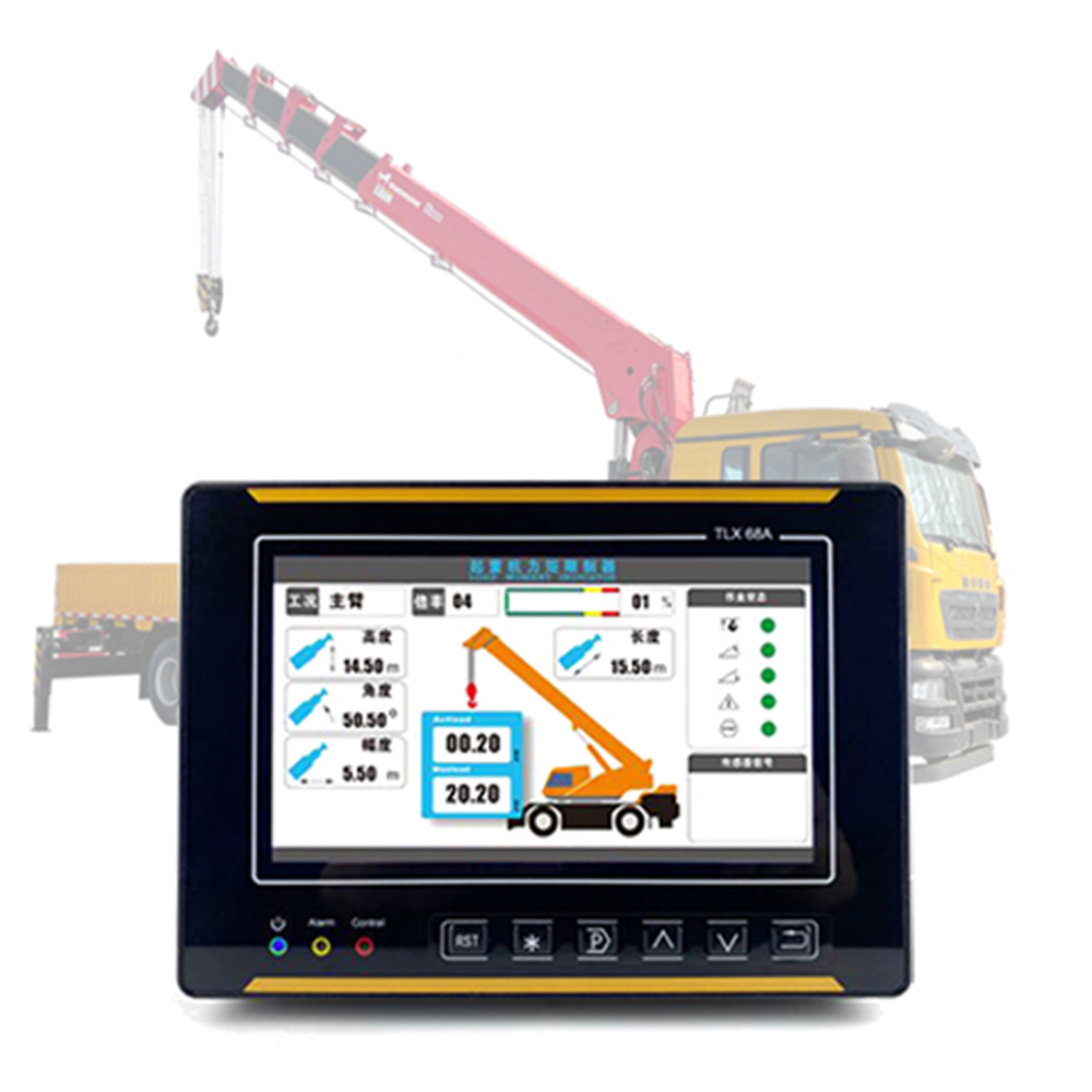
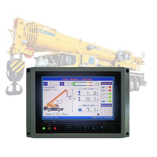
Le indicateur de moment de charge de grue (également connu sous le nom de indicateur de charge de sécurité de la grue,appelé «grue LMILe dispositif de sécurité est un dispositif obligatoire, exigé par la norme GB 6067.1-2010. La qualité de son installation influence directement la précision de la surveillance et la réponse du système de contrôle de sécurité. Conformément à la norme GB/T 12602-2022 « Dispositifs de protection contre les surcharges pour machines de levage », les points essentiels suivants doivent être respectés lors de l'installation :
I. Préparation technique et environnementale préliminaire
- Vérification de la correspondance des paramètres
Vérifiez la plaque signalétique de la grue LMI par rapport aux documents techniques de la grue pour vous assurer que les paramètres de base tels que le moment nominal, le rayon maximal et la classification de la longueur de la flèche sont cohérents. Pour les grues à flèche relevable, il est nécessaire de vérifier l'adaptabilité entre la plage de mesure du capteur de rayon (angle d'élévation de 0° à 80°) et l'angle de la flèche, avec une erreur de ≤ ± 0,5°.
- Gestion de la compatibilité électromagnétique
Détectez l'environnement électromagnétique de la zone d'installation afin de vous assurer que le champ magnétique à fréquence industrielle est ≤ 50 Hz/100 μT. Le câble du capteur doit être à paire torsadée blindée (couche de blindage ≥ 0,5 mm²) avec mise à la terre à une extrémité (résistance de mise à la terre ≤ 4 Ω) afin d'éviter tout couplage électromagnétique avec le système de commande électrique.
II. Contrôle de précision pour l'installation des composants principaux
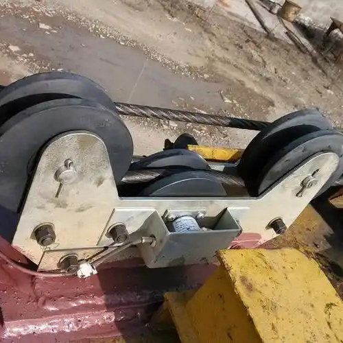
- Positionnement du capteur
Capteur de poids : il doit être proche du point porteur du groupe de crochets pour assurer la force verticale et garantir que l'efficacité de transmission de la force axiale est ≥ 98 %.
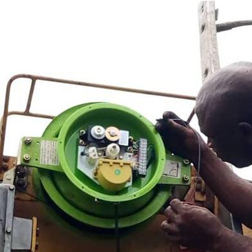
Capteur de longueur et d'angle : positionné à l'aide d'un projecteur laser. L'erreur de coaxialité entre l'axe de rotation et l'axe d'articulation de la flèche est ≤ 1 mm, et le délai de mesure d'angle est ≤ 50 ms.
- Exigences de fixation mécanique
La connexion entre le capteur et le corps de la machine doit être réalisée avec des boulons ajustés (GB/T 27) avec un ajustement de transition H7/k6. La force de pré-serrage des boulons de classe 8.8 doit être comprise entre 60 % et 70 % de la limite d'élasticité. Les grues mobiles doivent être équipées de patins antivibratoires (dureté 50 ± 5 Shore A) et la fréquence de résonance doit être inférieure à 10-50 Hz, ce qui est le cas des engins de chantier.
III. Spécifications d'intégration du système électrique
- Conception de câblage
Les lignes de signaux adoptent une topologie en étoile pour éviter l'atténuation du signal. La pose des câbles doit respecter les exigences suivantes : la distance par rapport aux câbles d'alimentation est ≥ 300 mm, et ils doivent se croiser à 90° ; le rayon de courbure est ≥ 10 fois supérieur au diamètre du câble et l'espacement des fixations est ≤ 500 mm ; la fiche est une fiche aéronautique IP67 avec une épaisseur de placage des broches ≥ 5 μm.
- Accès au circuit de sécurité
La sortie relais de la grue LMI est connectée au point normalement fermé du circuit de contrôle de sécurité pour garantir que lorsque la valeur surveillée atteint 110 % du moment nominal, l'alimentation électrique pour les directions de levage et d'extension de la flèche est coupée dans un délai ≤ 0,2 s. La section transversale du conducteur du circuit est ≥ 1,5 mm², utilisant un câble à âme en cuivre ignifuge GB/T 5023.5.
IV. Exigences d'étalonnage et d'acceptation
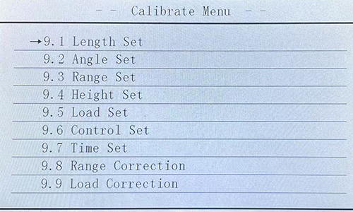
- Calibrage multi-conditions
Conformément à l'annexe C de la norme GB/T 12602-2022, étalonner aux rayons minimum, moyen et maximum sous des charges nominales de 10 %, 50 % et 100 %. Utiliser un dynamomètre standard de classe 0,1 et un codeur angulaire d'une résolution de 0,01° pour collecter les données, en s'assurant que l'écart entre la valeur affichée et la valeur standard est ≤ ± 2 %.
- Acceptation et maintenance
Après l'installation, les documents suivants doivent être fournis : rapport de détection des coordonnées 3D du capteur, relevé de la résistance d'isolement du circuit électrique (état froid ≥ 100 MΩ, état chaud ≥ 1 MΩ), courbe d'étalonnage et tableau d'erreurs. Lors de l'entretien quotidien, utilisez des poids étalons pour revérifier le point de charge nominale à 100 % tous les trimestres et effectuez un étalonnage complet tous les ans ; après des réparations importantes, il est nécessaire de revérifier la précision de l'installation et les paramètres d'étalonnage.
Le respect des spécifications ci-dessus peut garantir que la grue LMI fonctionne de manière stable dans des conditions de travail de -20℃~60℃ et une humidité relative ≤95% (sans condensation), répondant aux exigences de sécurité de la norme GB 50490-2009.