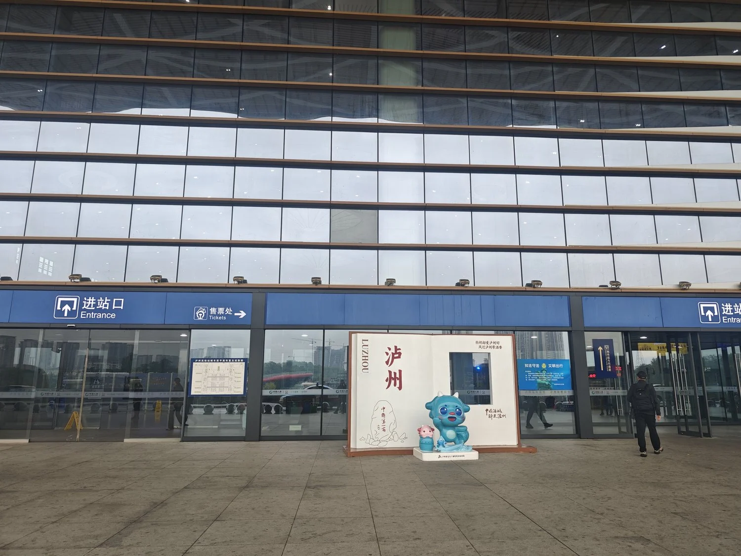
26–28 октября 2026 года два инженера компании SeeZol находились на заводе Sichuan Bangli Heavy Machinery в городе Лучжоу (провинция Сычуань), где занимались установкой индикатора момента нагрузки на 140-тонный гусеничный погрузчик с ковшовым захватом. Надстройка расположена на приподнятом портале, благодаря чему точка поворота стрелы находится на высоте 10 м над землей; рабочий радиус машины составляет 25 м. Почти к каждой точке крепления приходилось добираться с помощью подъемника на стреле, и ничто не могло быть установлено на глаз. Было установлено пять датчиков — датчик положения корпуса, датчик угла наклона стрелы, датчик угла наклона рукояти и два датчика давления на цилиндре стрелы — которые передают данные на блок сбора данных SZ-E01, взаимодействующий по протоколу CANopen с новым терминалом LMI-8000 под управлением Linux. Далее следуют обследование, определение точек крепления, прокладка жгута проводов, калибровка и три деталя, которые, по нашему мнению, определят, сохранятся ли показания в октябре следующего года.
1. Где это произошло и что это за устройство
Бангли — компания «Сычуань Бангли Хеви Машинери Ко., Лтд.», расположенная в высокотехнологичном промышленном парке города Лучжоу на берегу реки Янцзы, ведет свою историю от завода по производству экскаваторов «Чанцзян». В 1977 году компания начала производство экскаватора Liebherr R961 по лицензии, а в 1985 году — полного комплекта R962 / R972 / R982, а в настоящее время управляет заводом площадью 400 000 м² с численностью персонала около 500 человек, производящим гидравлические экскаваторы грузоподъемностью 6,5–220 т и погрузочно-разгрузочные машины грузоподъемностью 10–200 т. В компании внедрены стандарты ISO 9001, ISO 14001 и ISO 45001, а технический центр имеет статус провинциального уровня.
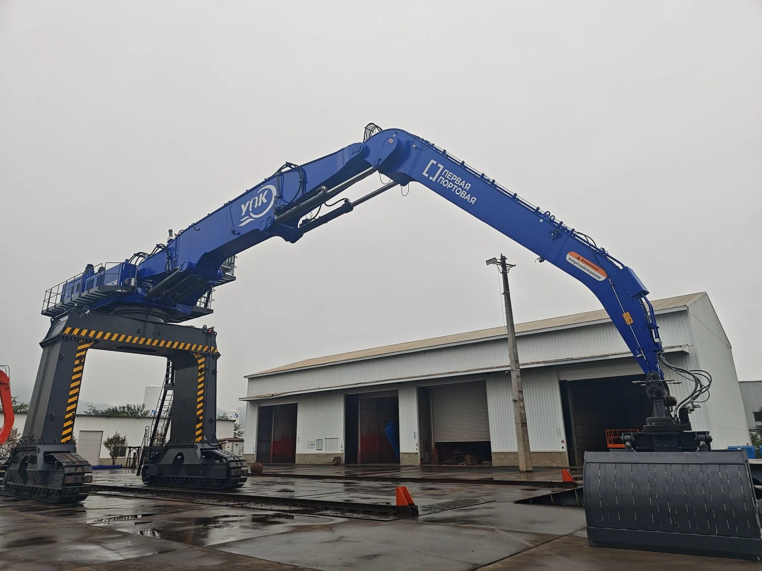
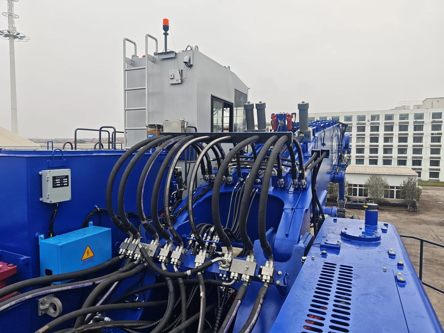
Машина, стоящая на площадке, представляет собой 140-тонный погрузчик с грейферным захватом, установленный на приподнятой гусеничной портальной раме. Две гусеничные дорожки, сварная портальная рама и надстройка, расположенная высоко над этой рамой — приподнятая с учетом условий работы на объекте, благодаря чему точка поворота стрелы находится на высоте 10 м над землей. Стрела типа «гусиная шея», гидравлический грейфер для обломков и кабина, расположенная низко на надстройке, благодаря чему оператор смотрит вдоль стрелы, а не вниз на неё. На стреле нанесена символика конечного заказчика: логотип YNK и надписи на русском языке.
Две цифры определяют всю работу. Шарнир соединения стрелы с корпусом находится на высоте 10 м над землей — не потому, что стрела настолько длинная, а потому, что корпус установлен на подъемной опоре — и при полном выдвижении машина достигает высоты 25 м. Таблица нагрузок составлена с учетом высоты от уровня земли, поэтому обе величины напрямую влияют на расчет радиуса и высоты; кроме того, обе обеспечивают расположение датчиков значительно выше места, где заканчивается лестница. Ни одна операция с использованием индикатора момента нагрузки на такой высоте не может выполняться силами одного человека.
2. Почему 25-метровый погрузчик оказывает большее давление на индикатор момента нагрузки, чем мобильный кран
Автокран — это простая в измерении машина: один шарнир, одна телескопическая стрела, трос с известным коэффициентом усиления и тензодатчик на конце стрелы. А у погрузчика с ковшом-захватом ничего подобного нет.
Радиус не является функцией одного угла. Стрела представляет собой «гусиную шею» с дополнительным шарниром, а рукоять поворачивается на собственном шарнире. Точное положение грейфера зависит от угла наклона стрелы, угла наклона рукояти и положения самого грейфера в совокупности. Один градус угла наклона стрелы на расстоянии 25 м соответствует радиусу 25 × π / 180 ≈ 0,44 м — а 0,44 м при номинальной нагрузке 10,9 т даёт момент силы примерно 4,8 т·м. Решите эту задачу с двумя углами, и показания датчиков дальности смещаются на метры.
Машина никогда не стоит ровно. Гусеничный портал устанавливается на любом покрытии площадки — будь то асфальт, щебень или уплотнённый край отвала — и на две гусеницы никогда не приходится одинаковая нагрузка. Угол крена в один-два градуса считается нормальным, и он меняется по мере движения машины и перераспределения нагрузки на грунт под ней. Подъемная опора усугубляет, а не улучшает ситуацию: при высоте оси поворота 10 м один градус крена смещает её на 0,17 м вбок и примерно на столько же по высоте, и оба этих значения напрямую влияют на пересчёт радиуса и высоты. Система, исходящая из горизонтального положения, переносит эту погрешность на каждое показание смещения. Отсюда и необходимость датчика положения кузова: измерять крен и тангаж и корректировать, а не делать допущения.
Веревки нет. Нагрузка должна создаваться за счет давления в цилиндре, а это означает наличие двух камер, трение уплотнений и контур, заполненный клапанами. Давление не является показателем нагрузки до тех пор, пока оно не будет откалибровано с учетом радиуса, к тому же оно изменяется в зависимости от температуры масла, поэтому для такого типа индикатора момента нагрузки требуется более одной точки калибровки в пределах рабочего диапазона.
Система разработана в соответствии со стандартом ISO 10245-1 для ограничительных и сигнализирующих устройств, стандартом GB/T 12602 для защиты от перегрузки подъемных механизмов, а также стандартом EN 13000 в тех странах, куда осуществляется экспорт оборудования. Эти стандарты определяют, что должно делать устройство — предупреждать и, при необходимости, останавливать. Они не гарантируют точность показаний. Эту задачу выполняют проверка и калибровка — именно поэтому перед тем, как кто-либо откроет экран настроек, индикатор момента нагрузки требует целого дня измерений.
3. Что мы установили: терминал индикатора момента нагрузки на базе Linux и его цепь датчиков
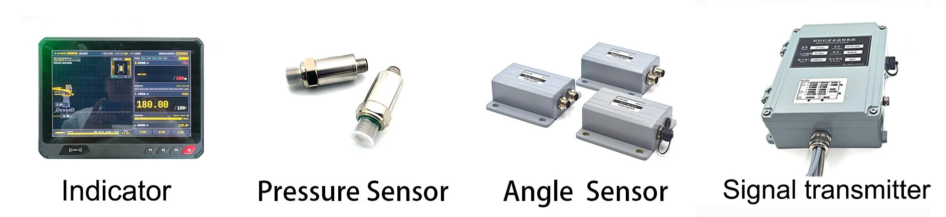
Индикатор момента нагрузки на этой машине относится к текущему поколению, и изменения в нём выходят за рамки простой замены экрана. В предыдущем поколении использовалась плата микроконтроллера с фиксированной прошивкой: дисплей отображал момент и угол, набор параметров записывался на заводе, и любое изменение требовало создания новой версии прошивки. Терминал LMI-8000 в этой кабине представляет собой компьютер на базе Linux. Калибровка осуществляется через экран, по которому оператор проходит шаг за шагом; язык и единицы измерения настраиваются, а не заложены в сборке, а журналы представляют собой файлы, которые можно скопировать из кабины.
Разделение функций между двумя блоками является целенаправленным. Оценка безопасности — пороговые значения перегрузки, управление реле, решение о блокировке движения — остается в блоке сбора данных SZ-E01, который представляет собой детерминированный контроллер реального времени, работающий по протоколу CANopen. Терминал на базе Linux отвечает за отображение информации, ведение журнала и взаимодействие с пользователем. Linux предоставляет удобный пользовательский интерфейс, хранилище данных и сетевой стек; однако он не гарантирует ограниченное время отклика после «холодного» запуска. Сохранение функции отключения в блоке сбора данных означает, что терминал можно перезагружать, заменять или обновлять без потери машиной защиты от перегрузки даже на один цикл.
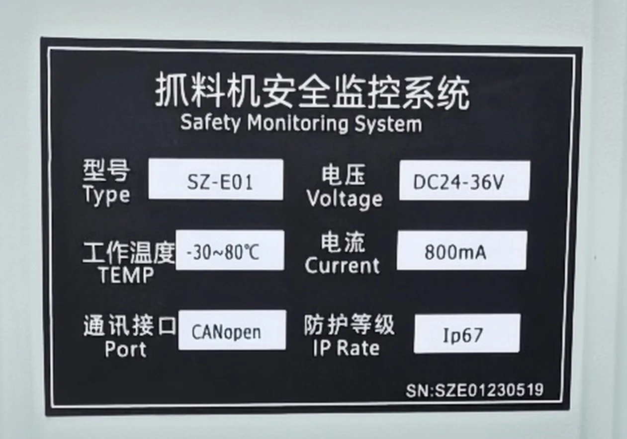
Табличка с техническими данными на агрегате, сфотографированная на самой машине, — это именно та информация, которую стоит привести, поскольку это единственная характеристика на этой странице, взятая непосредственно с металла, а не из технического паспорта.
| Пункт | Значение | Источник |
|---|---|---|
| Блок сбора данных / блок управления | SZ-E01 | Паспортная табличка |
| Терминал отображения | LMI-8000, платформа Linux | Экран терминала |
| Напряжение питания | 24–36 В постоянного тока | Паспортная табличка |
| Потребляемый ток | 800 мА | Паспортная табличка |
| Рабочая температура | от −30 °C до +80 °C | Паспортная табличка |
| Полевая шина | CANopen на устройстве; CAN-соединение с терминалом, синхронизированное | Табличка с названием + строка состояния экрана |
| Степень защиты от проникновения | IP67 | Паспортная табличка |
| Серийный номер устройства | SZE01230519 | Паспортная табличка |
| Номинальная системная погрешность | ±3 % | Данные о продукте SeeZol |
| Канал | Модель | Дальность / точность | Точка крепления |
|---|---|---|---|
| Поза тела | SZ-A01BD | ±10–90°, 0,1° в абсолютном выражении, разрешение 0,05°, IP67 | Поворотная платформа, обработанная опорная площадка, оси выровнены по системе координат станка |
| Угол наклона стрелы | SZ-A01BM | Same family, 9–36 VDC, 0.02 s response | Boom web above the root hinge, machined pad |
| Stick angle | SZ-A01AM | Same family | Stick root hinge |
| Boom cylinder, piston side (P1) | SZ-P201S-400 | 0–400 bar, 4–20 mA, 0.5 % F.S., 0.1 bar | Adaptor block at the cylinder head end |
| Boom cylinder, rod side (P2) | SZ-P201S-400 | 0–400 bar, 4–20 mA, 0.5 % F.S., 0.1 bar | Valve block test port, boom cylinder circuit |
Two error figures on this load moment indicator have to be kept apart. The transmitter is 0.5 % F.S., which on a 400 bar range is 2 bar. The system figure is ±3 %, which at a rated 10.9 t is ±0.33 t. The first describes one channel’s linearity; the second includes geometry, calibration and hydraulic friction. Quote the second to a customer, never the first — and never let a tender document mix them.
4. How a material handler load moment indicator gets installed, sensor by sensor
Five channels make up this material handler load moment indicator, and each one answers a different question: where the platform is, where the boom is, where the stick is, and how hard the cylinder is pushing from each side. Get any one of them wrong and the others cannot compensate.
4.1 Angle channels: body, boom, stick
Three angle sensors on this load moment indicator, all from the SZ-A01 family: 9–36 VDC, 0.1° absolute accuracy, 0.05° resolution, 0.02 s response, IP67. Each one is a gravity reference, so each one has to be mounted to a surface whose relationship with the machine’s geometry is known and stable.
Body (SZ-A01BD). A machined pad on the slewing platform, aligned to the machine’s longitudinal and transverse axes. This channel exists to serve the second problem in section 2: it measures how far the gantry is off level, and the controller uses that to correct radius and height. On a crawler machine that walks onto unprepared ground and gets packed up under the tracks before a lift, it is not a nicety.
Boom (SZ-A01BM). On the boom web, a short distance above the root hinge, on a pad machined after the boom was welded. This one is a gravity reference, so what it needs is not a mechanism but a surface whose angle to the boom centreline is known and does not change. A welded boom web is not that surface: across the footprint of the sensor it is out of flat by more than the 0.1° the sensor is specified to. So the pad is machined, the sensor is bolted down to it, and the cable leaves downward into a drip loop before it is clipped along the web at the same pitch as the hose clamps.
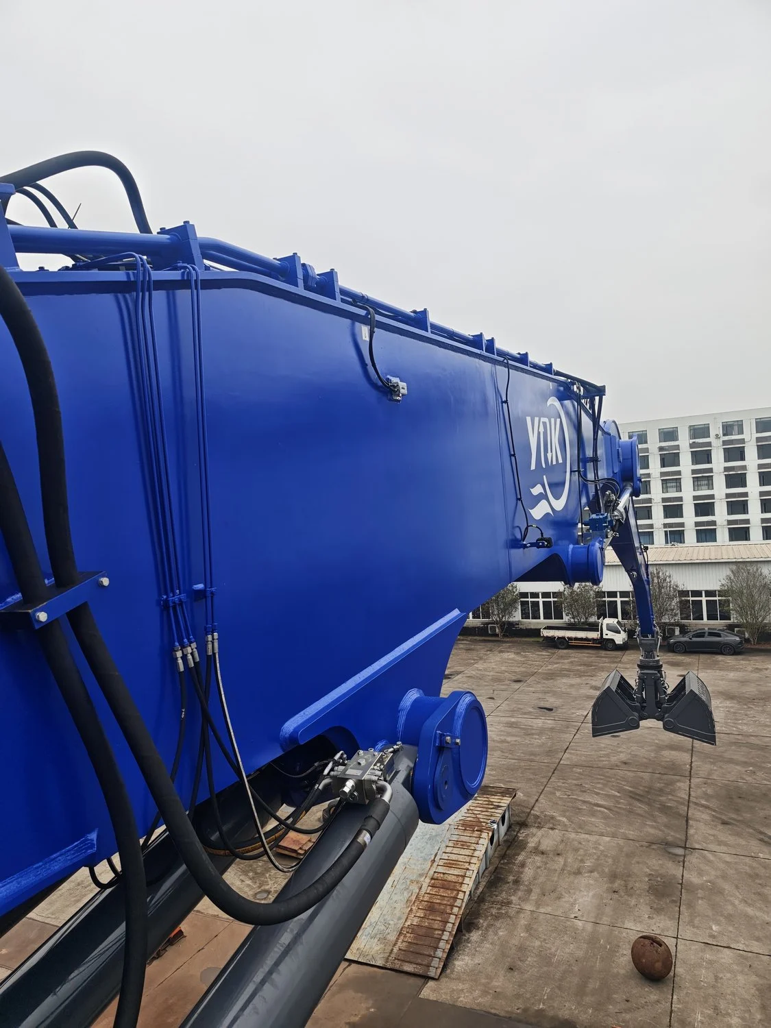
Stick (SZ-A01AM). Same arrangement at the stick root. This is the channel a two-angle crane load moment indicator does not have, and on this machine it is not optional: with a gooseneck boom and a stick that swings on its own hinge, boom angle alone cannot tell the controller where the grab is.
4.2 Pressure channels P1 and P2
The pressure side of a hydraulic load moment indicator is where its accuracy is actually won or lost. Two SZ-P201S transmitters, 0–400 bar, 4–20 mA, on the boom cylinder circuit: P1 on the piston side, P2 on the rod side. Neither is taken by cutting a hose. P1 comes off a machined adaptor block bolted at the cylinder head end, which puts the transmitter on a flat face at the piston-side gallery and keeps it clear of the hose bundle; P2 comes off a test port on the valve block, where the rod-side gallery is already brought out. Fewer joints in a 35 MPa circuit, and both points isolate for service without draining anything.
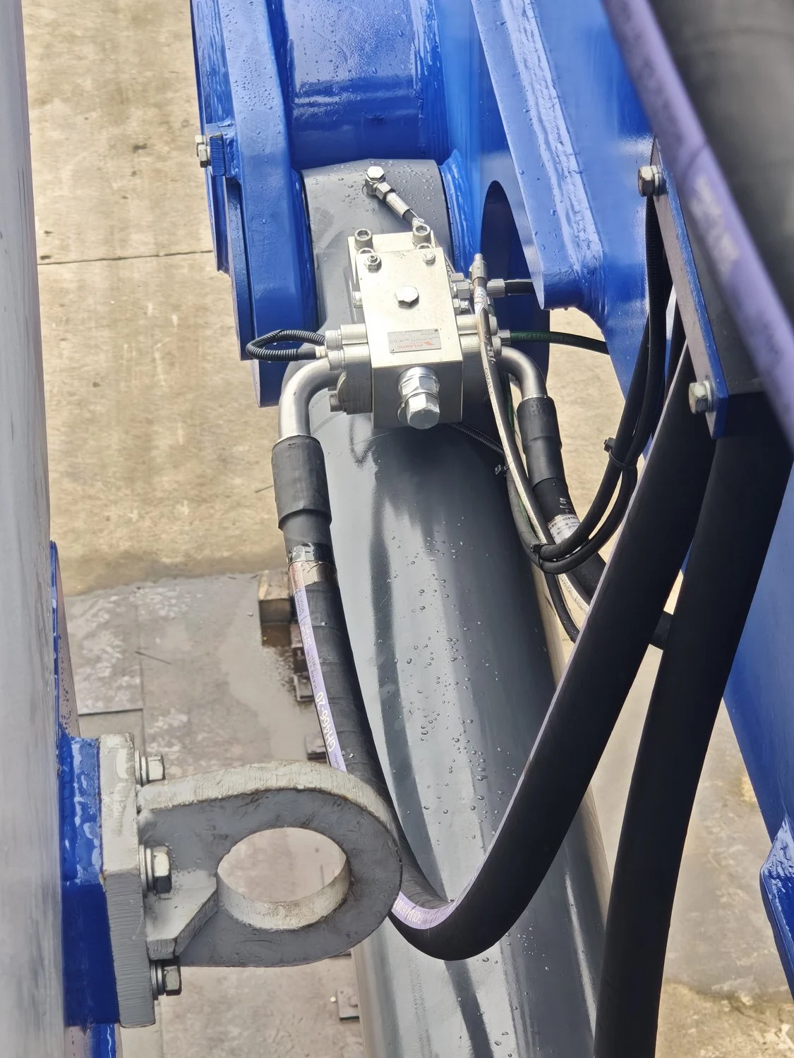
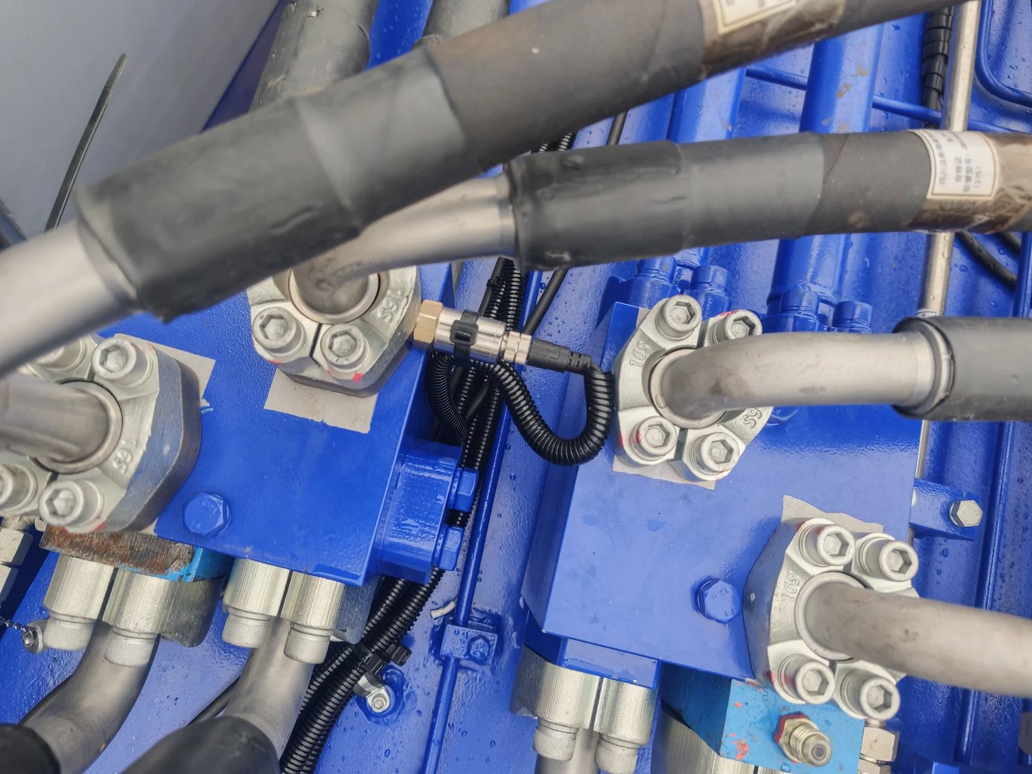
Two channels rather than one, because the boom cylinder is differential. Piston-side pressure alone gives force in one direction only; with the rod-side channel the controller can subtract the annulus area and the return-line back pressure. A grab machine spends half its cycle holding a load at reach and half swinging empty, and without that subtraction the empty swing reads as a few hundred kilos of load that is not there.
Practical note: P2 sits at low pressure most of the time, so it is the channel that suffers first when there is air in the line. Bleed both, then zero. A bubble in the rod-side line shows up as a zero that drifts for the first hour of every shift, and operators learn to distrust the display long before anyone thinks to bleed it.
4.3 Acquisition unit and junction boxes
The SZ-E01 — the box that does the arithmetic behind the load moment indicator — sits in a die-cast enclosure on the superstructure side wall, high up under the handrail, away from the spray path of the return filter. Below it is the machine’s own cable box, and to one side the two red valve blocks of the boom circuit.
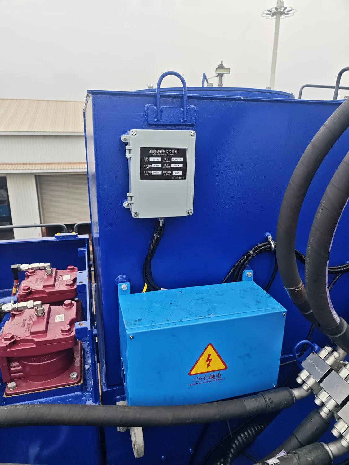
Mounting rules we do not bend at this height: glands facing down, enclosure on standoffs so water runs behind it instead of pooling at the gasket, stainless fasteners with threadlocker, and cable entry on the underside even when the top is easier to reach from the lift.
4.4 Harness: ten metres up, and it has to survive the swing
Both the sensors and the display are on the rotating half of the machine, so the run never crosses the rotary joint — a real advantage over a portal crane with the cab on the fixed side. The hard part is the boom root: two hinges’ worth of relative motion inside half a metre, next to a bundle of hoses that flex every cycle.
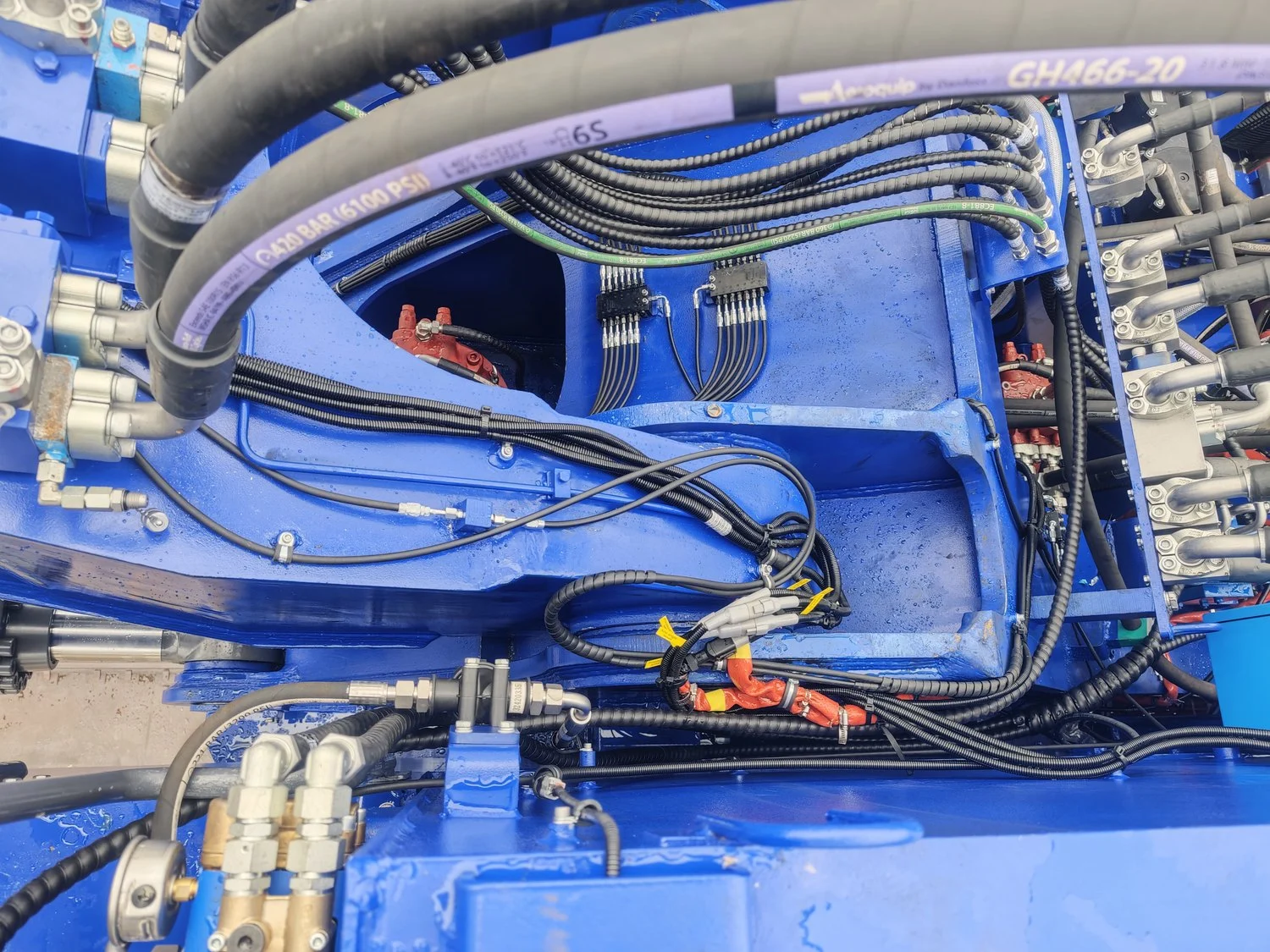
Split corrugated conduit on the existing clamps, a service loop at each hinge, a drip loop before every gland, and Deutsch-style connectors at the boom root. That last item is not about reliability. It is about the day the machine goes on a lowbed: the boom comes off, and nobody should be cutting a sensor cable to make that happen.
4.5 The display in the cab
The load moment indicator terminal, an LMI-8000, sits on the right-hand post, in the operator’s sight line when the grab is at reach. The F1–F3 keys under the screen are physical, which is the right call: this operator wears gloves all day, and a capacitive panel through a work glove is a bad interface.
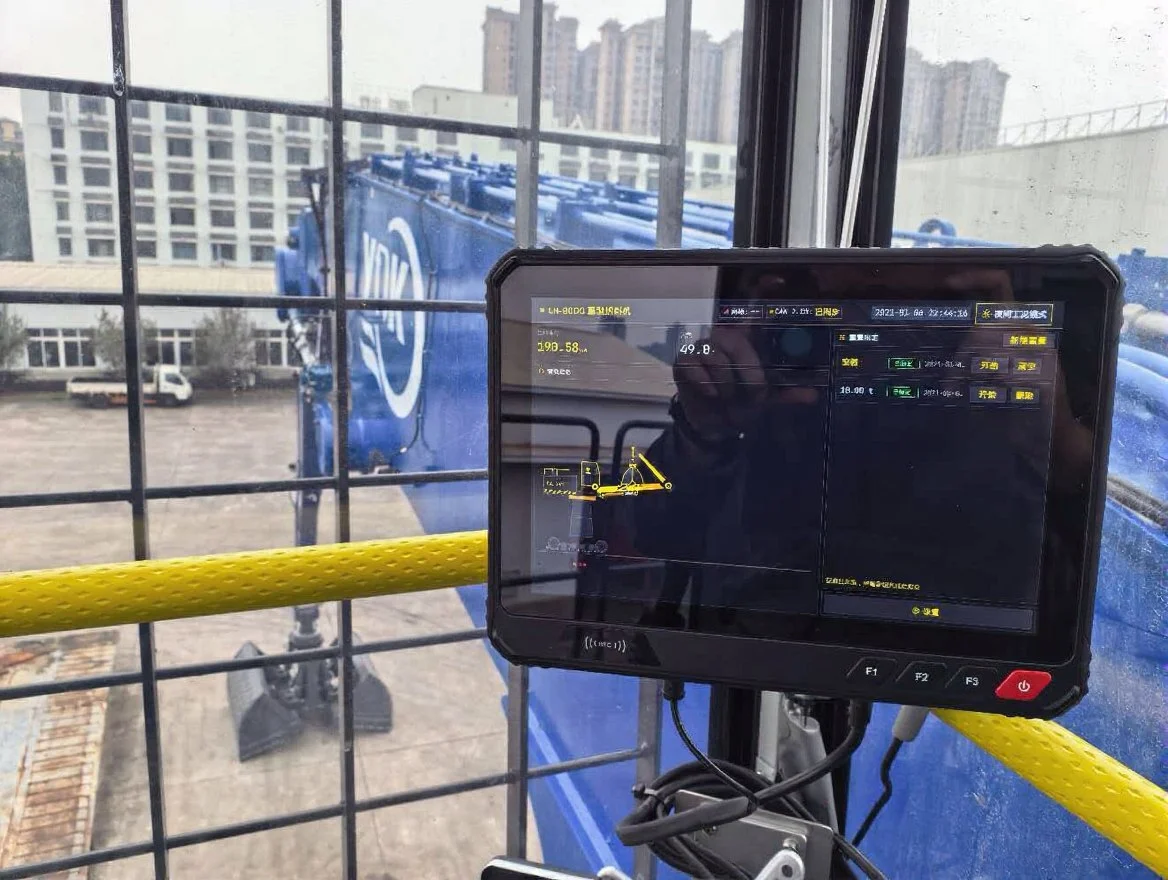
What the screen was showing at that moment: the CAN link synchronised with the acquisition unit, boom at 49.8°, and the calibration page with two records — empty and 18.00 t — both flagged as calibrated. Night mode is a single button on the status bar; it drops the panel to a dark palette and dims the backlight, which matters on a night shift with the cab lights off and a glare-free windscreen.
The network field is empty on this machine. The terminal supports it; the yard did not ask for remote access, and we do not switch on a network stack that nobody is going to administer. If they want log uploads later, the terminal already has the interface — that is a cab job, not a machine job.
5. Calibration: geometry first, then two points
Installation is the easy half of a load moment indicator job. On a machine this size the geometry is where the error hides, so before anyone touched the calibration page we measured.
Check 1 — radius. Tape from the slew centre to the grab pin at three boom angles, compared against the geometry model. This is the check that catches a sensor bracket fitted against the wrong datum face, before it turns into a calibration offset nobody can explain three months later.
Check 2 — zero. Grab empty, machine levelled on packers under the tracks, boom at mid-range, both pressure channels bled and then zeroed. Zeroing with the grab resting on the ground is the classic mistake: you zero in the weight of the grab that the ground is carrying, and the machine carries a constant offset for the rest of its life.
Check 3 — loaded point. One known load of 18.00 t, taken at three radii. That is the second calibration record on the screen in Fig. 12. Two points — empty and one known load — fix the gain. The third radius is what tells you whether the stick channel is doing its job or just adding noise.
Then the part that does not appear in any acceptance document: half an hour with the operator. What the alarm means, what a bypass does and does not allow, and how to tell a real overload from a sensor fault. On a grab machine the operator is the only person who looks at this display all day. If he does not trust it, he will ignore it — and an ignored load moment indicator is worse than no indicator, because it puts a number on a decision that used to be made with judgement.
6. Field notes: three things that decide whether this load moment indicator still reads true next October
1. Water follows cable, not gravity. It rained for two of the three days. Every photograph in this report has water on the paint. The three failures that follow rain on a machine like this are a gland facing up, a drip loop that is actually a U-trap, and a connector boot that was pushed on but not locked. All three are invisible at commissioning and all three show up as an intermittent angle channel six months later.
2. Air in the rod-side line. P2 is the channel that gets forgotten, because it reads near zero most of the day and nobody notices it drifting. Bleed it at commissioning, bleed it again after the first week of work, and note in the handover that a zero which walks is air before it is a failed sensor.
3. The clock and the calibration file. The screen in Fig. 12 reads 2021-09-06 22:44:36 — the factory default real-time clock, not the day of the job — and both calibration records carry that same date. It is harmless on the day. A year later, when someone is trying to work out which sensor was replaced and when, a file in which every event happened on the same September evening is worth nothing. Set the clock at commissioning, export the calibration file, and file it with the machine’s records. On a Linux terminal that export is a USB stick and thirty seconds; on the old fixed-firmware display it was a service laptop and a phone call.
7. What the customer actually received
The delivered material handler load moment indicator consists of three angle sensors (body, boom, stick), two pressure transmitters, one SZ-E01 acquisition unit, one LMI-8000 terminal, the harness with hinge service loops and Deutsch connectors at the boom root, mounting brackets, the drawing set (mounting positions and wiring), the calibration record, a spare connector and gland kit, and half an hour of operator briefing.
Three relay outputs, K1–K3, are available on the acquisition unit of this load moment indicator for motion cut-off, and the harness for it is part of the standard build. Whether to enable cut-off on a grab machine is the customer’s call, not ours: some yards want the boom to slow at the threshold, others want it to stop, and a few want alarm only during the first months of operation while operators get used to the display. What the system must not do is decide that on the customer’s behalf.
What a load moment indicator means in the yard, in plain terms: the operator gets a load and radius reading before the grab leaves the pile instead of after the machine feels light on one side; the yard gets a per-cycle log it can reconcile against inbound and outbound tonnage; and a machine going out to a new site carries its calibration record with it instead of a technician’s memory.
8. FAQ: load moment indicator questions from this job
Can we invoice off this load moment indicator instead of a weighbridge? No. It is a safety device with a ±3 % system figure; on a 10.9 t rated load that is ±0.33 t. A trade weighbridge is an order of magnitude tighter and legally verified. Use this to prevent overloads and to log trends, and invoice on a certified scale.
Why three angle sensors when cranes use two? Because the boom is a gooseneck and the stick swings on its own hinge. Two angles cannot resolve where the grab is at 25 m. The third channel is what makes the radius reading a measurement rather than an estimate.
Does moving the display to Linux weaken the safety function? Not if the safety logic stays in the real-time acquisition unit, which is how this load moment indicator is built. The terminal displays, logs and takes input. The trip decision is made in the SZ-E01 and driven out through its relays.
How long does installation take on a machine this size? Two working days is the typical figure for the mechanical and electrical work, plus calibration; on this machine the high-reach mounting set the schedule, not the wiring. Machines with the cab on the fixed side and a slip ring in the path take longer.
Can we keep an older machine and only change the display? Usually yes, if the acquisition unit’s CANopen protocol matches the terminal’s. But recalibrate anyway. A new terminal running an old calibration file is the most common way to end up with a number that looks right and is not.
9. Tell us the machine, we will come back with a configuration
For a quotation that is not guesswork we need six numbers: rated capacity, boom pivot height, maximum reach, boom and stick cylinder bore and rod diameter, relief pressure, and whether the machine is for protection only or also for internal weighing. With those, a configuration and a mounting sketch come back within one working day.
About this report. Written by the SeeZol field engineering team from site records and photographs taken at the Sichuan Bangli Heavy Machinery works, Luzhou, 26–28 October 2026. System design of this load moment indicator references ISO 10245-1, GB/T 12602 and EN 13000. All figures in Table 1 were read off the unit nameplate or the terminal screen on site; component data in Table 2 comes from SeeZol product documentation.
Рекомендуемые материалы: the 300-ton port grab installation at Huanghai Machinery · how to choose a load moment indicator in five steps · oil pressure sensor installation guide · material handler load indicator product page · LMI selection by machine type