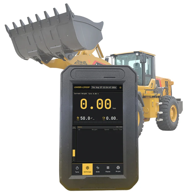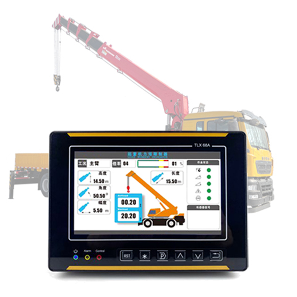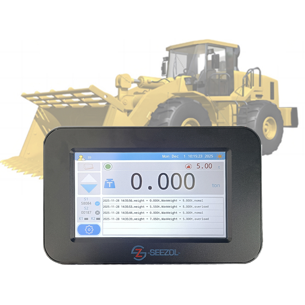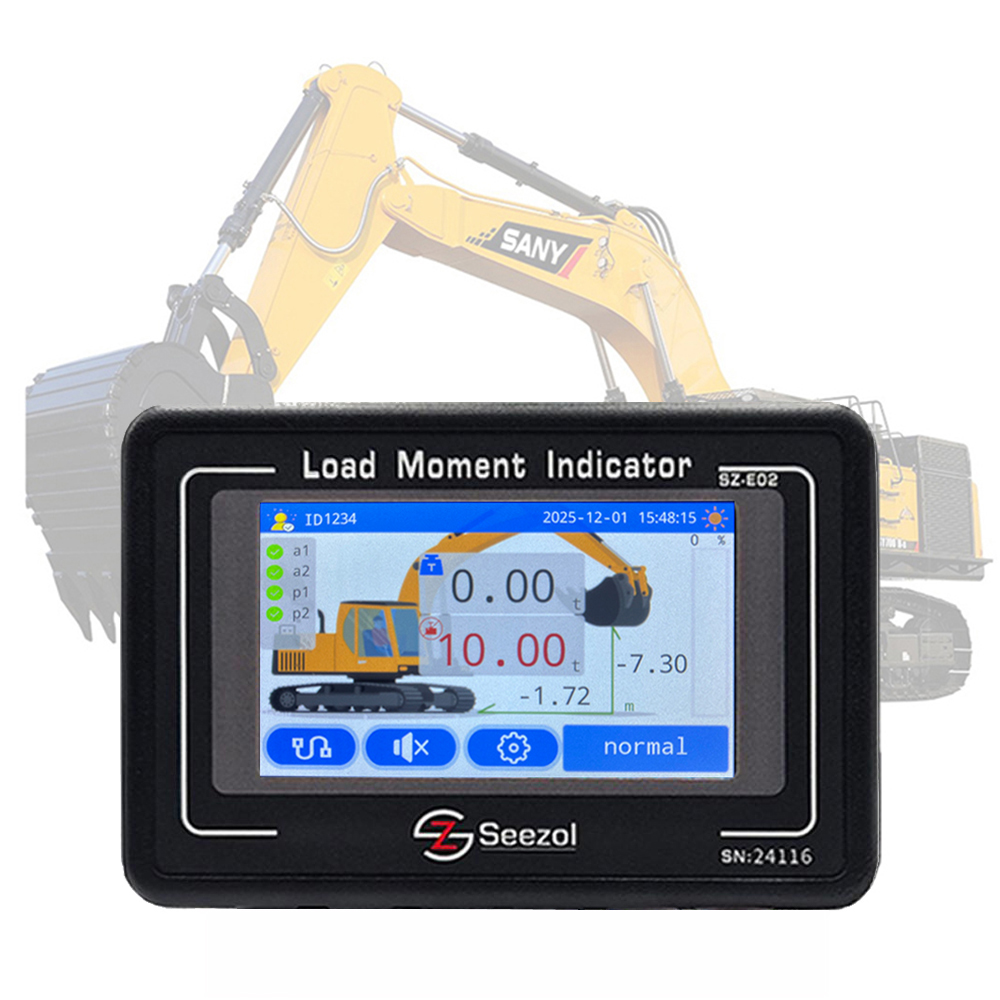
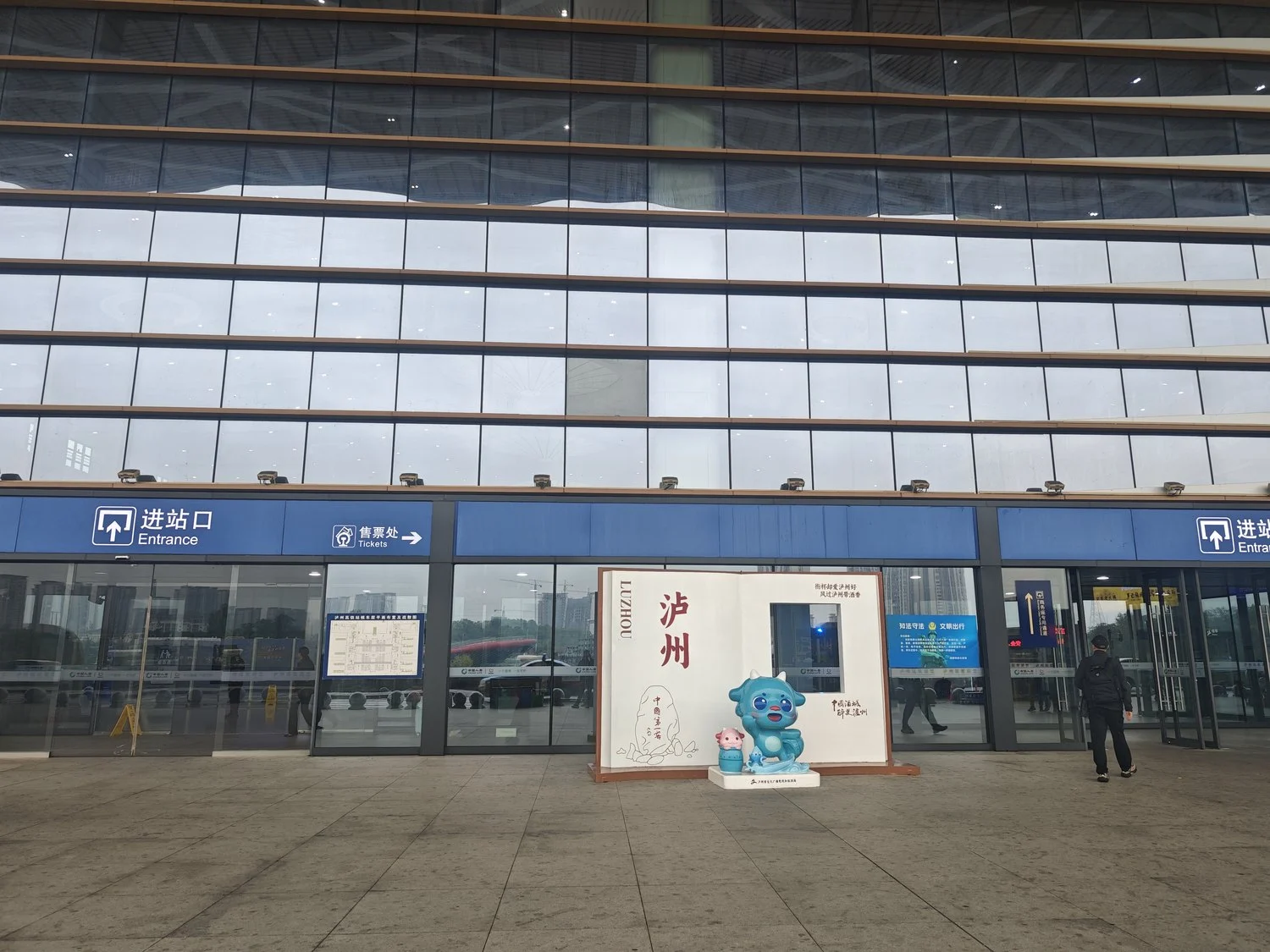
Del 26 al 28 de octubre de 2026, dos ingenieros de SeeZol se desplazaron a las instalaciones de Sichuan Bangli Heavy Machinery en Luzhou, Sichuan, para instalar un indicador de momento de carga en una cargadora sobre orugas de 140 toneladas equipada con una cuchara de concha. La superestructura se asienta sobre un pórtico elevado, lo que sitúa el pivote de la pluma a 10 m del suelo; la máquina alcanza los 25 m. Para acceder a casi todos los puntos de montaje fue necesario utilizar una plataforma elevadora, y no fue posible colocar nada a ojo. Se instalaron cinco sensores —de actitud del cuerpo, ángulo de la pluma, ángulo de la palanca y dos canales de presión en el cilindro de la pluma— que envían datos a una unidad de adquisición SZ-E01 que se comunica a través de CANopen con el nuevo terminal LMI-8000 con sistema operativo Linux. A continuación se describen el estudio topográfico, los puntos de montaje, el mazo de cables, la calibración y los tres detalles que, en nuestra opinión, determinarán si las lecturas siguen siendo válidas el próximo mes de octubre.
1. Dónde ocurrió y qué máquina es
Bangli — Sichuan Bangli Heavy Machinery Co., Ltd., situada en el parque industrial de alta tecnología de Luzhou, a orillas del Yangtsé — tiene sus orígenes en la fábrica de excavadoras Changjiang. La empresa fabricó bajo licencia la Liebherr R961 en 1977 y adquirió la licencia completa para los modelos R962 / R972 / R982 en 1985, y actualmente cuenta con una planta de 400 000 m² y una plantilla de aproximadamente 500 empleados, donde fabrica excavadoras hidráulicas de entre 6,5 y 220 t y manipuladores de materiales de entre 10 y 200 t. Cuenta con las certificaciones ISO 9001, ISO 14001 e ISO 45001, y su centro técnico tiene categoría provincial.
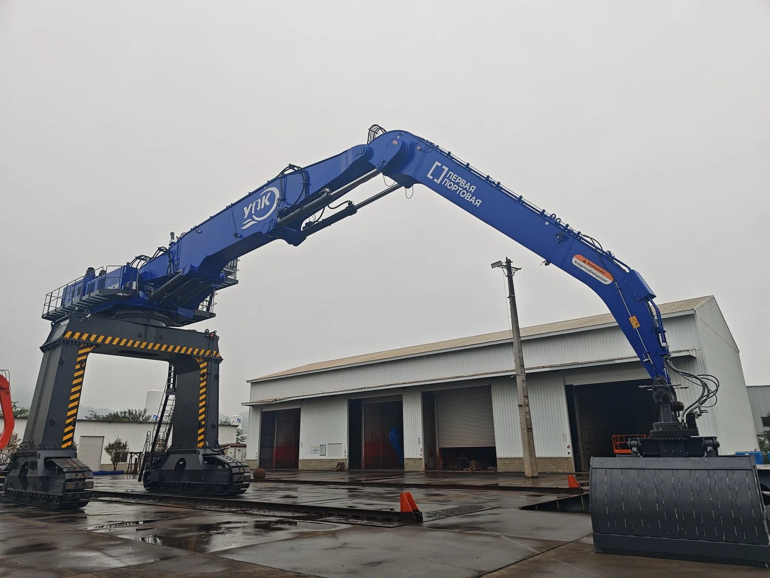
La máquina que se encuentra en el patio es una grúa con pinza para conchas de 140 toneladas montada sobre un pórtico elevable sobre orugas. Cuenta con dos cadenas de oruga, un bastidor en pórtico fabricado y la superestructura situada en lo alto de dicho bastidor —elevada para adaptarse al entorno de trabajo de la obra, lo que sitúa el pivote de la pluma a 10 m sobre el suelo—. Pluma tipo «cuello de cisne», pinza hidráulica para conchas y cabina situada en la parte baja de la superestructura, de modo que el operador mira a lo largo de la pluma en lugar de hacia abajo. La pluma lleva los distintivos del cliente final: el logotipo de YNK y letras en ruso.
Hay dos cifras que determinan todo el trabajo. La articulación entre la pluma y el chasis se encuentra a 10 m del suelo —no porque la pluma sea tan larga, sino porque el chasis se apoya sobre un elevador— y la máquina alcanza los 25 m en su máxima extensión. La tabla de cargas se elabora desde el nivel del suelo, por lo que ambas cifras influyen directamente en la conversión de radio y altura; y ambas sitúan las placas de los sensores muy por encima de donde termina una escalera. En un trabajo con indicador de momento de carga a esta altura, nada se puede realizar por una sola persona.
2. Por qué una manipuladora de materiales de 25 m ejerce más presión sobre un indicador de momento de carga que una grúa móvil
Una grúa sobre camión es una máquina fácil de equipar: una articulación, una pluma telescópica, un cable con un multiplicador conocido y una célula de carga en el extremo. Una pala de agarre no te ofrece nada de eso.
El radio no es una función de un ángulo. La pluma es de tipo «cuello de cisne» con una articulación adicional, y la palanca gira sobre su propia bisagra. El punto exacto en el que cuelga la pinza depende conjuntamente del ángulo de la pluma, el ángulo de la palanca y la posición de la pinza. Un grado de ángulo de la pluma a 25 m corresponde a un radio de 25 × π / 180 ≈ 0,44 m, y 0,44 m con una carga nominal de 10,9 t supone aproximadamente un momento de 4,8 t·m. Si se calcula esto con dos ángulos, las lecturas de alcance se desvían en metros.
La máquina nunca está nivelada. Una grúa pórtico sobre orugas se apoya sobre cualquier tipo de suelo del patio —pavimento, grava, el borde compactado de un montón de material— y las dos orugas nunca soportan la misma carga. Es habitual que se produzca un balanceo de entre uno y dos grados, y este varía a medida que la máquina avanza y el suelo que hay debajo soporta el peso. El elevador empeora la situación en lugar de mejorarla: con el pivote a 10 m de altura, un grado de balanceo lo desplaza 0,17 m lateralmente y aproximadamente lo mismo en altura, y ambas cifras se incorporan directamente a la conversión de radio y altura. Un sistema que asume que el terreno está nivelado transmite ese error a cada lectura del desplazamiento. De ahí la importancia del sensor de actitud de la carrocería: medir el balanceo y la inclinación y corregirlos, en lugar de dar por sentado que todo está nivelado.
No hay cuerda. La carga debe provenir de la presión del cilindro, lo que implica dos cámaras, la fricción de las juntas y un circuito repleto de válvulas. La presión no es un indicador de la carga hasta que se calibra en función del radio, y varía con la temperatura del aceite; por eso, este tipo de indicador de momento de carga necesita más de un único punto de calibración a lo largo del rango de trabajo.
El sistema está diseñado de acuerdo con la norma ISO 10245-1 para dispositivos de limitación e indicación, la norma GB/T 12602 para la protección contra sobrecargas en aparatos de elevación y la norma EN 13000 en los países a los que se exporta la máquina. Dichas normas establecen lo que el dispositivo debe hacer —avertir y, cuando sea necesario, detener—. No se encargan de que los valores sean correctos. De eso se encargan el estudio y la calibración; por eso, un indicador de momento de carga requiere un día de mediciones antes de que nadie pueda acceder a la pantalla de configuración.
3. Lo que hemos instalado: un terminal indicador de momento de carga con Linux y su cadena de sensores
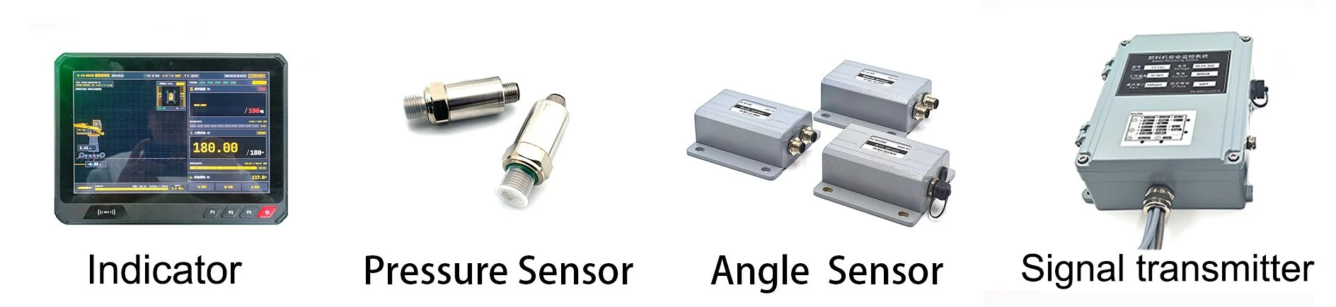
El indicador de momento de carga de esta máquina es de la generación actual, y el cambio va más allá de una simple pantalla nueva. La generación anterior consistía en una placa de microcontrolador con firmware fijo: la pantalla mostraba el momento y el ángulo, los parámetros se programaban de fábrica y cualquier cambio suponía crear una nueva versión del firmware. El terminal LMI-8000 de esta cabina es un equipo con Linux. La calibración se realiza a través de una pantalla que se va completando paso a paso con el operador; el idioma y las unidades son ajustes configurables en lugar de versiones fijas, y los registros son archivos que se pueden copiar fuera de la cabina.
La separación entre las dos cajas es deliberada. Las decisiones de seguridad —umbrales de sobrecarga, accionamiento de relés, la decisión de inhibir un movimiento— se mantienen en la unidad de adquisición SZ-E01, que es un controlador determinista en tiempo real sobre CANopen. El terminal Linux se encarga de la visualización, el registro y la interfaz de usuario. Linux aporta una interfaz de usuario usable, capacidad de almacenamiento y una pila de red; no garantiza un tiempo de respuesta limitado tras un arranque en frío. Mantener la desconexión en la unidad de adquisición significa que el terminal puede reiniciarse, sustituirse o actualizarse sin que la máquina pierda la protección contra sobrecargas ni siquiera durante un ciclo.
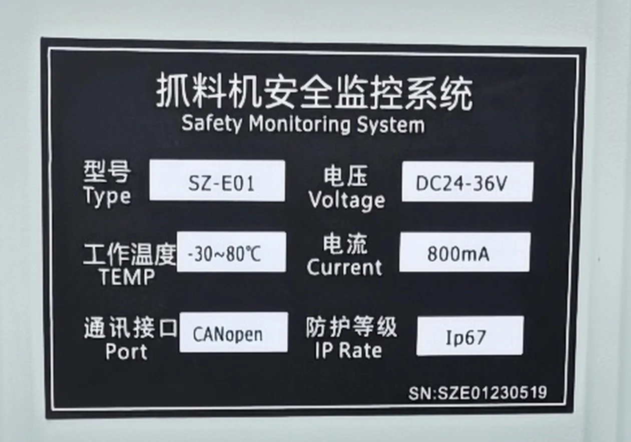
La placa de características de la unidad, fotografiada en la propia máquina, es la parte que merece la pena citar, ya que es la única especificación de esta página que procede directamente del metal y no de una ficha técnica.
| Artículo | Valor | Fuente |
|---|---|---|
| Unidad de adquisición/control | SZ-E01 | Placa de identificación |
| Terminal de visualización | LMI-8000, plataforma Linux | Pantalla del terminal |
| Tensión de alimentación | 24-36 V CC | Placa de identificación |
| Consumo de corriente | 800 mA | Placa de identificación |
| Temperatura de funcionamiento | De −30 °C a +80 °C | Placa de identificación |
| Bus de campo | CANopen en la unidad; conexión CAN al terminal, sincronizada | Placa de identificación + barra de estado de la pantalla |
| Protección contra la entrada de elementos | IP67 | Placa de identificación |
| Número de serie de la unidad | SZE01230519 | Placa de identificación |
| Error nominal del sistema | ±3 % | Datos del producto SeeZol |
| Canal | Modelo | Alcance / precisión | Punto de montaje |
|---|---|---|---|
| Postura corporal | SZ-A01BD | ±10–90°, 0,1° absoluto, resolución de 0,05°, IP67 | Plataforma giratoria, base mecanizada, ejes alineados con el punto de referencia de la máquina |
| Ángulo de la pluma | SZ-A01BM | Same family, 9–36 VDC, 0.02 s response | Boom web above the root hinge, machined pad |
| Stick angle | SZ-A01AM | Same family | Stick root hinge |
| Boom cylinder, piston side (P1) | SZ-P201S-400 | 0–400 bar, 4–20 mA, 0.5 % F.S., 0.1 bar | Adaptor block at the cylinder head end |
| Boom cylinder, rod side (P2) | SZ-P201S-400 | 0–400 bar, 4–20 mA, 0.5 % F.S., 0.1 bar | Valve block test port, boom cylinder circuit |
Two error figures on this load moment indicator have to be kept apart. The transmitter is 0.5 % F.S., which on a 400 bar range is 2 bar. The system figure is ±3 %, which at a rated 10.9 t is ±0.33 t. The first describes one channel’s linearity; the second includes geometry, calibration and hydraulic friction. Quote the second to a customer, never the first — and never let a tender document mix them.
4. How a material handler load moment indicator gets installed, sensor by sensor
Five channels make up this material handler load moment indicator, and each one answers a different question: where the platform is, where the boom is, where the stick is, and how hard the cylinder is pushing from each side. Get any one of them wrong and the others cannot compensate.
4.1 Angle channels: body, boom, stick
Three angle sensors on this load moment indicator, all from the SZ-A01 family: 9–36 VDC, 0.1° absolute accuracy, 0.05° resolution, 0.02 s response, IP67. Each one is a gravity reference, so each one has to be mounted to a surface whose relationship with the machine’s geometry is known and stable.
Body (SZ-A01BD). A machined pad on the slewing platform, aligned to the machine’s longitudinal and transverse axes. This channel exists to serve the second problem in section 2: it measures how far the gantry is off level, and the controller uses that to correct radius and height. On a crawler machine that walks onto unprepared ground and gets packed up under the tracks before a lift, it is not a nicety.
Boom (SZ-A01BM). On the boom web, a short distance above the root hinge, on a pad machined after the boom was welded. This one is a gravity reference, so what it needs is not a mechanism but a surface whose angle to the boom centreline is known and does not change. A welded boom web is not that surface: across the footprint of the sensor it is out of flat by more than the 0.1° the sensor is specified to. So the pad is machined, the sensor is bolted down to it, and the cable leaves downward into a drip loop before it is clipped along the web at the same pitch as the hose clamps.
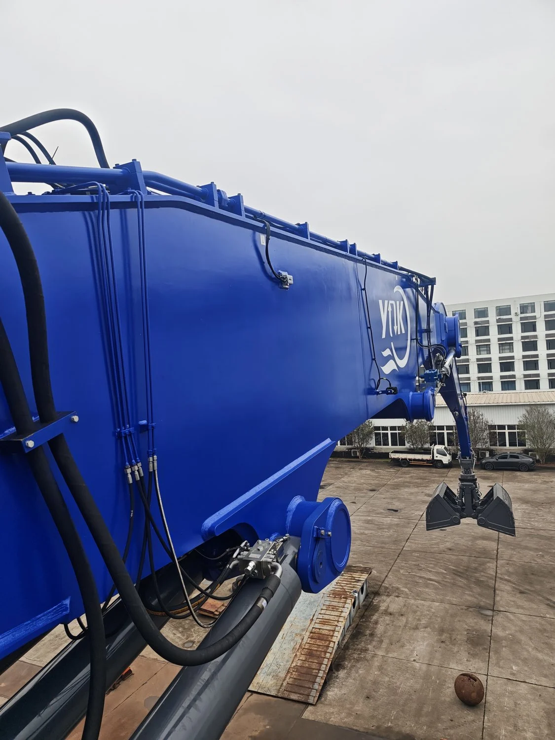
Stick (SZ-A01AM). Same arrangement at the stick root. This is the channel a two-angle crane load moment indicator does not have, and on this machine it is not optional: with a gooseneck boom and a stick that swings on its own hinge, boom angle alone cannot tell the controller where the grab is.
4.2 Pressure channels P1 and P2
The pressure side of a hydraulic load moment indicator is where its accuracy is actually won or lost. Two SZ-P201S transmitters, 0–400 bar, 4–20 mA, on the boom cylinder circuit: P1 on the piston side, P2 on the rod side. Neither is taken by cutting a hose. P1 comes off a machined adaptor block bolted at the cylinder head end, which puts the transmitter on a flat face at the piston-side gallery and keeps it clear of the hose bundle; P2 comes off a test port on the valve block, where the rod-side gallery is already brought out. Fewer joints in a 35 MPa circuit, and both points isolate for service without draining anything.
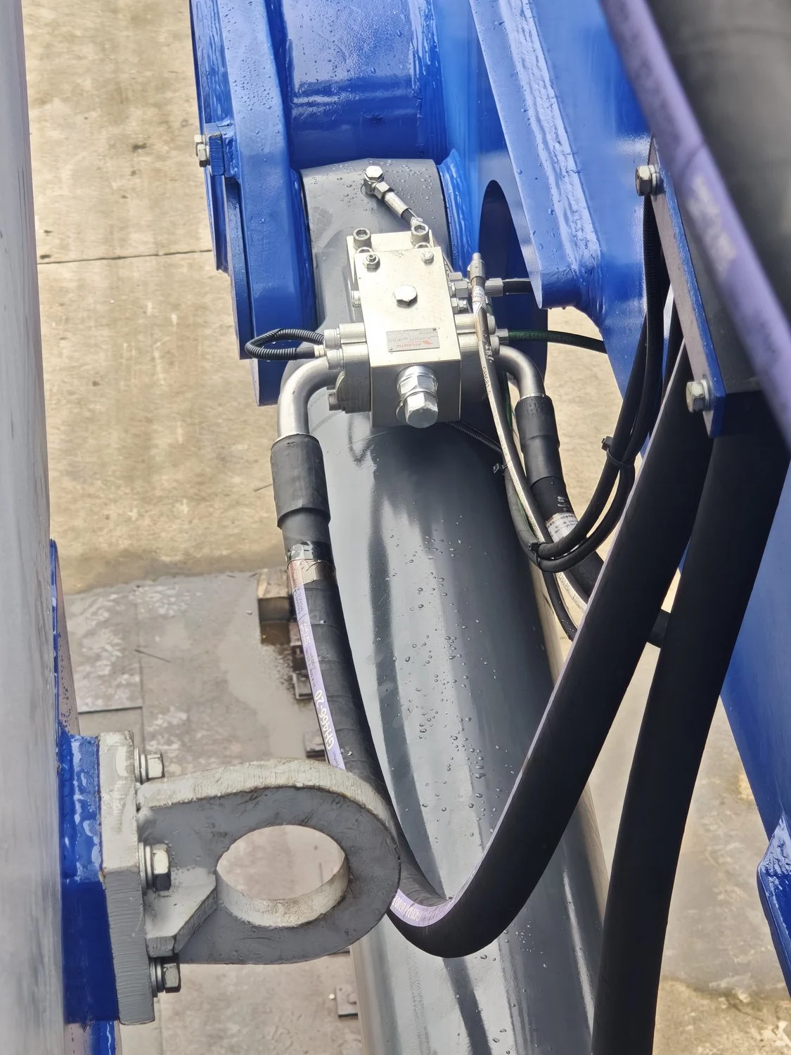
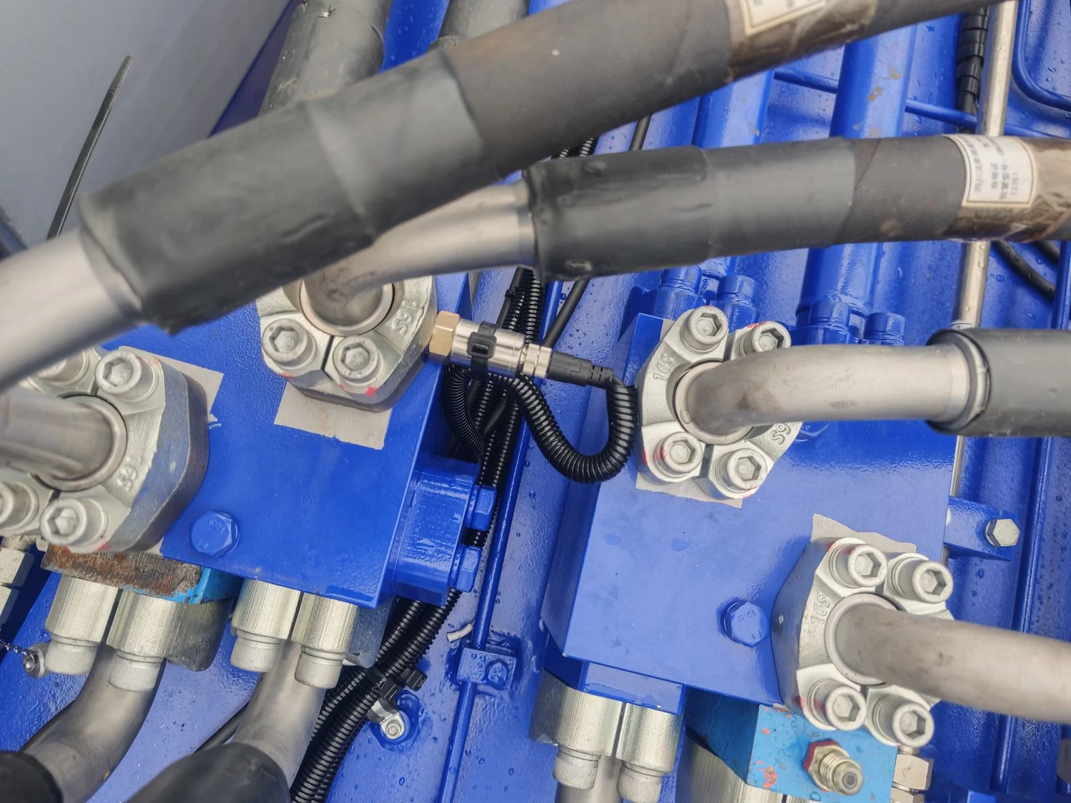
Two channels rather than one, because the boom cylinder is differential. Piston-side pressure alone gives force in one direction only; with the rod-side channel the controller can subtract the annulus area and the return-line back pressure. A grab machine spends half its cycle holding a load at reach and half swinging empty, and without that subtraction the empty swing reads as a few hundred kilos of load that is not there.
Practical note: P2 sits at low pressure most of the time, so it is the channel that suffers first when there is air in the line. Bleed both, then zero. A bubble in the rod-side line shows up as a zero that drifts for the first hour of every shift, and operators learn to distrust the display long before anyone thinks to bleed it.
4.3 Acquisition unit and junction boxes
The SZ-E01 — the box that does the arithmetic behind the load moment indicator — sits in a die-cast enclosure on the superstructure side wall, high up under the handrail, away from the spray path of the return filter. Below it is the machine’s own cable box, and to one side the two red valve blocks of the boom circuit.
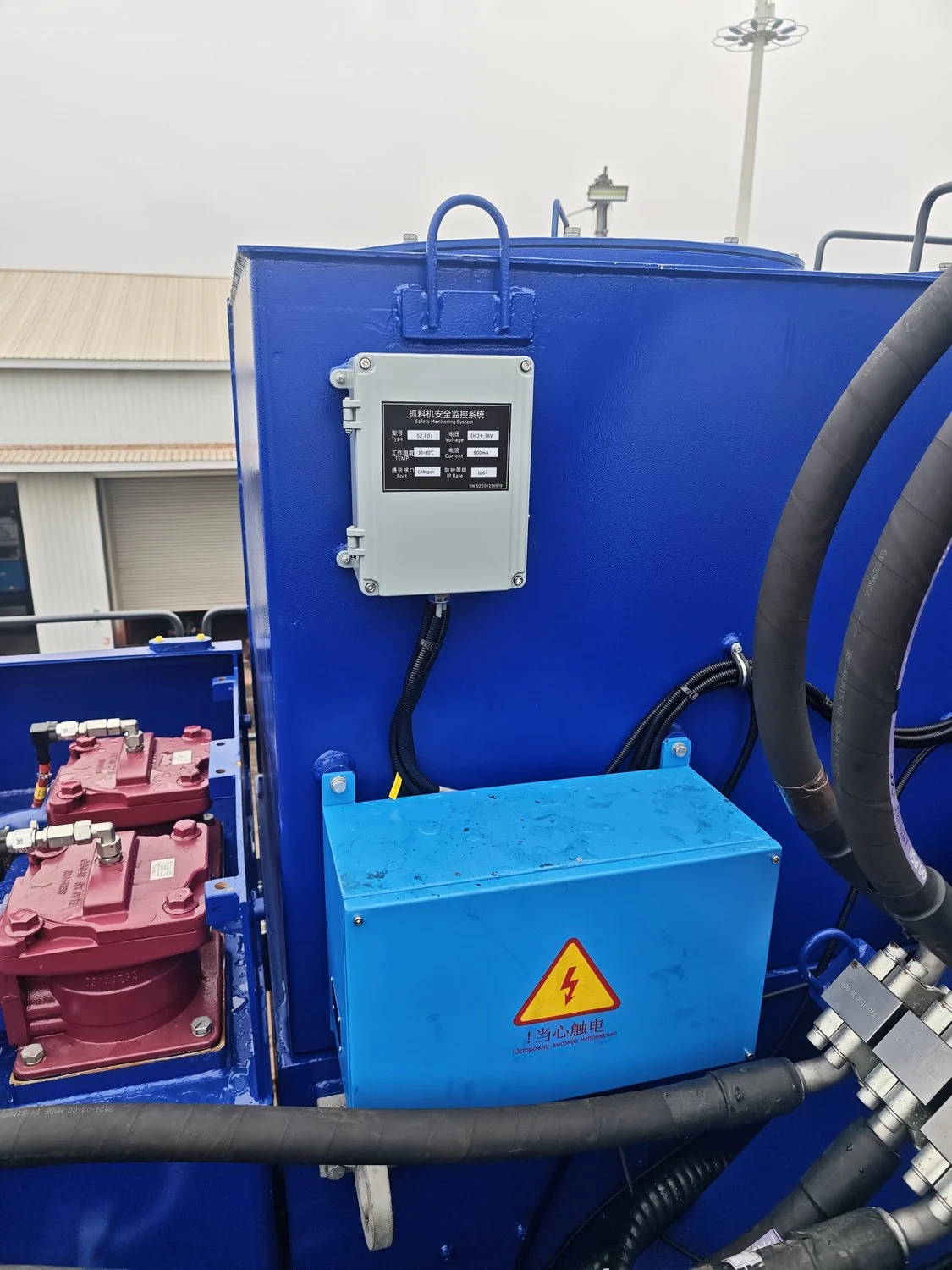
Mounting rules we do not bend at this height: glands facing down, enclosure on standoffs so water runs behind it instead of pooling at the gasket, stainless fasteners with threadlocker, and cable entry on the underside even when the top is easier to reach from the lift.
4.4 Harness: ten metres up, and it has to survive the swing
Both the sensors and the display are on the rotating half of the machine, so the run never crosses the rotary joint — a real advantage over a portal crane with the cab on the fixed side. The hard part is the boom root: two hinges’ worth of relative motion inside half a metre, next to a bundle of hoses that flex every cycle.
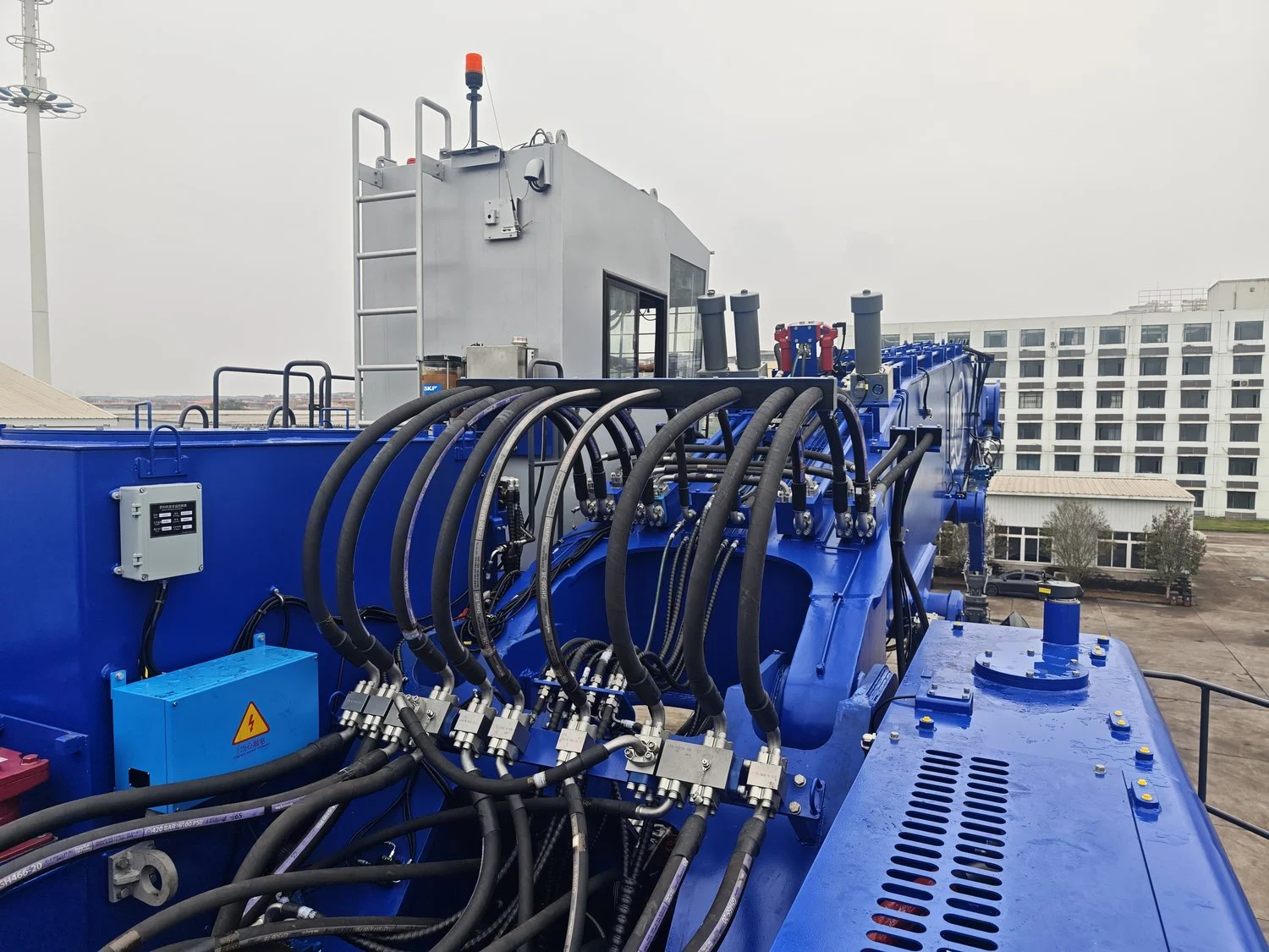
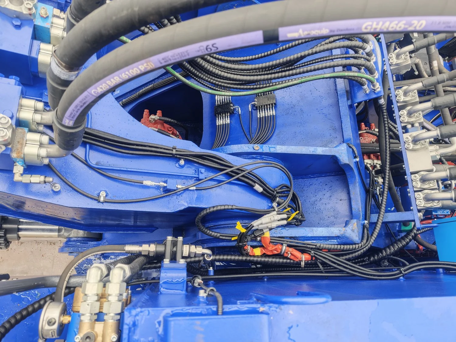
Split corrugated conduit on the existing clamps, a service loop at each hinge, a drip loop before every gland, and Deutsch-style connectors at the boom root. That last item is not about reliability. It is about the day the machine goes on a lowbed: the boom comes off, and nobody should be cutting a sensor cable to make that happen.
4.5 The display in the cab
The load moment indicator terminal, an LMI-8000, sits on the right-hand post, in the operator’s sight line when the grab is at reach. The F1–F3 keys under the screen are physical, which is the right call: this operator wears gloves all day, and a capacitive panel through a work glove is a bad interface.
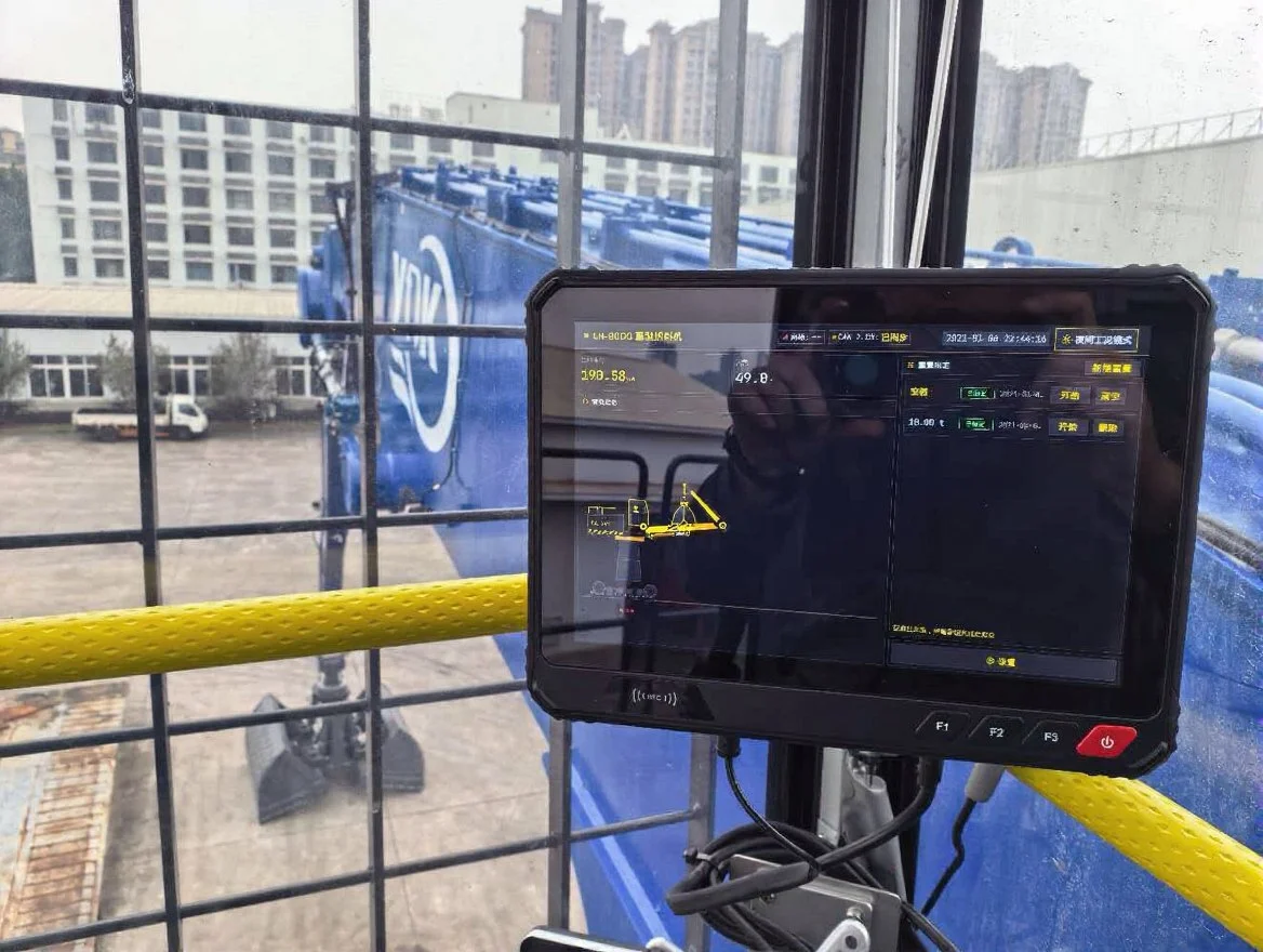
What the screen was showing at that moment: the CAN link synchronised with the acquisition unit, boom at 49.8°, and the calibration page with two records — empty and 18.00 t — both flagged as calibrated. Night mode is a single button on the status bar; it drops the panel to a dark palette and dims the backlight, which matters on a night shift with the cab lights off and a glare-free windscreen.
The network field is empty on this machine. The terminal supports it; the yard did not ask for remote access, and we do not switch on a network stack that nobody is going to administer. If they want log uploads later, the terminal already has the interface — that is a cab job, not a machine job.
5. Calibration: geometry first, then two points
Installation is the easy half of a load moment indicator job. On a machine this size the geometry is where the error hides, so before anyone touched the calibration page we measured.
Check 1 — radius. Tape from the slew centre to the grab pin at three boom angles, compared against the geometry model. This is the check that catches a sensor bracket fitted against the wrong datum face, before it turns into a calibration offset nobody can explain three months later.
Check 2 — zero. Grab empty, machine levelled on packers under the tracks, boom at mid-range, both pressure channels bled and then zeroed. Zeroing with the grab resting on the ground is the classic mistake: you zero in the weight of the grab that the ground is carrying, and the machine carries a constant offset for the rest of its life.
Check 3 — loaded point. One known load of 18.00 t, taken at three radii. That is the second calibration record on the screen in Fig. 12. Two points — empty and one known load — fix the gain. The third radius is what tells you whether the stick channel is doing its job or just adding noise.
Then the part that does not appear in any acceptance document: half an hour with the operator. What the alarm means, what a bypass does and does not allow, and how to tell a real overload from a sensor fault. On a grab machine the operator is the only person who looks at this display all day. If he does not trust it, he will ignore it — and an ignored load moment indicator is worse than no indicator, because it puts a number on a decision that used to be made with judgement.
6. Field notes: three things that decide whether this load moment indicator still reads true next October
1. Water follows cable, not gravity. It rained for two of the three days. Every photograph in this report has water on the paint. The three failures that follow rain on a machine like this are a gland facing up, a drip loop that is actually a U-trap, and a connector boot that was pushed on but not locked. All three are invisible at commissioning and all three show up as an intermittent angle channel six months later.
2. Air in the rod-side line. P2 is the channel that gets forgotten, because it reads near zero most of the day and nobody notices it drifting. Bleed it at commissioning, bleed it again after the first week of work, and note in the handover that a zero which walks is air before it is a failed sensor.
3. The clock and the calibration file. The screen in Fig. 12 reads 2021-09-06 22:44:36 — the factory default real-time clock, not the day of the job — and both calibration records carry that same date. It is harmless on the day. A year later, when someone is trying to work out which sensor was replaced and when, a file in which every event happened on the same September evening is worth nothing. Set the clock at commissioning, export the calibration file, and file it with the machine’s records. On a Linux terminal that export is a USB stick and thirty seconds; on the old fixed-firmware display it was a service laptop and a phone call.
7. What the customer actually received
The delivered material handler load moment indicator consists of three angle sensors (body, boom, stick), two pressure transmitters, one SZ-E01 acquisition unit, one LMI-8000 terminal, the harness with hinge service loops and Deutsch connectors at the boom root, mounting brackets, the drawing set (mounting positions and wiring), the calibration record, a spare connector and gland kit, and half an hour of operator briefing.
Three relay outputs, K1–K3, are available on the acquisition unit of this load moment indicator for motion cut-off, and the harness for it is part of the standard build. Whether to enable cut-off on a grab machine is the customer’s call, not ours: some yards want the boom to slow at the threshold, others want it to stop, and a few want alarm only during the first months of operation while operators get used to the display. What the system must not do is decide that on the customer’s behalf.
What a load moment indicator means in the yard, in plain terms: the operator gets a load and radius reading before the grab leaves the pile instead of after the machine feels light on one side; the yard gets a per-cycle log it can reconcile against inbound and outbound tonnage; and a machine going out to a new site carries its calibration record with it instead of a technician’s memory.
8. FAQ: load moment indicator questions from this job
Can we invoice off this load moment indicator instead of a weighbridge? No. It is a safety device with a ±3 % system figure; on a 10.9 t rated load that is ±0.33 t. A trade weighbridge is an order of magnitude tighter and legally verified. Use this to prevent overloads and to log trends, and invoice on a certified scale.
Why three angle sensors when cranes use two? Because the boom is a gooseneck and the stick swings on its own hinge. Two angles cannot resolve where the grab is at 25 m. The third channel is what makes the radius reading a measurement rather than an estimate.
Does moving the display to Linux weaken the safety function? Not if the safety logic stays in the real-time acquisition unit, which is how this load moment indicator is built. The terminal displays, logs and takes input. The trip decision is made in the SZ-E01 and driven out through its relays.
How long does installation take on a machine this size? Two working days is the typical figure for the mechanical and electrical work, plus calibration; on this machine the high-reach mounting set the schedule, not the wiring. Machines with the cab on the fixed side and a slip ring in the path take longer.
Can we keep an older machine and only change the display? Usually yes, if the acquisition unit’s CANopen protocol matches the terminal’s. But recalibrate anyway. A new terminal running an old calibration file is the most common way to end up with a number that looks right and is not.
9. Tell us the machine, we will come back with a configuration
For a quotation that is not guesswork we need six numbers: rated capacity, boom pivot height, maximum reach, boom and stick cylinder bore and rod diameter, relief pressure, and whether the machine is for protection only or also for internal weighing. With those, a configuration and a mounting sketch come back within one working day.
About this report. Written by the SeeZol field engineering team from site records and photographs taken at the Sichuan Bangli Heavy Machinery works, Luzhou, 26–28 October 2026. System design of this load moment indicator references ISO 10245-1, GB/T 12602 and EN 13000. All figures in Table 1 were read off the unit nameplate or the terminal screen on site; component data in Table 2 comes from SeeZol product documentation.
Lecturas relacionadas: the 300-ton port grab installation at Huanghai Machinery · how to choose a load moment indicator in five steps · oil pressure sensor installation guide · material handler load indicator product page · LMI selection by machine type