新闻与活动

深入解析起重机载荷力矩指示器(LMI):原理、构成及应用

Author: SEEZOL.
Disclosure: We accept no payment from LMI manufacturers to influence content, and no specific brand is endorsed here.

TL;DR

A 负载力矩指示器 (LMI) is a closed-loop electronic safety system that measures load weight, boom angle, and boom length several times per second, calculates the resulting load moment (force × distance), and compares it against the crane’s rated capacity chart — triggering staged warnings and, on most systems, automatic lockout before the crane exceeds its structural or tipping limit. It is a mandatory safety layer on cranes above a certain tonnage in most jurisdictions, but it is not a substitute for correct rigging, competent operation, or routine calibration — all three failure modes bypass the LMI entirely.

Contents

  1. Core Components
  2. Working Principle: From Data to Decision
  3. Worked Example: How the Math Actually Works
  4. System Classification: RCI, LMI, RCL, and Crane-Specific Variants
  5. Value and Limitations — an Honest Assessment
  6. Field Notes: What Actually Goes Wrong in Practice
  7. Maintenance-Essentials
  8. Where the Technology Is Headed
  9. 常见问题解答
  10. About This Article

1. Core Components

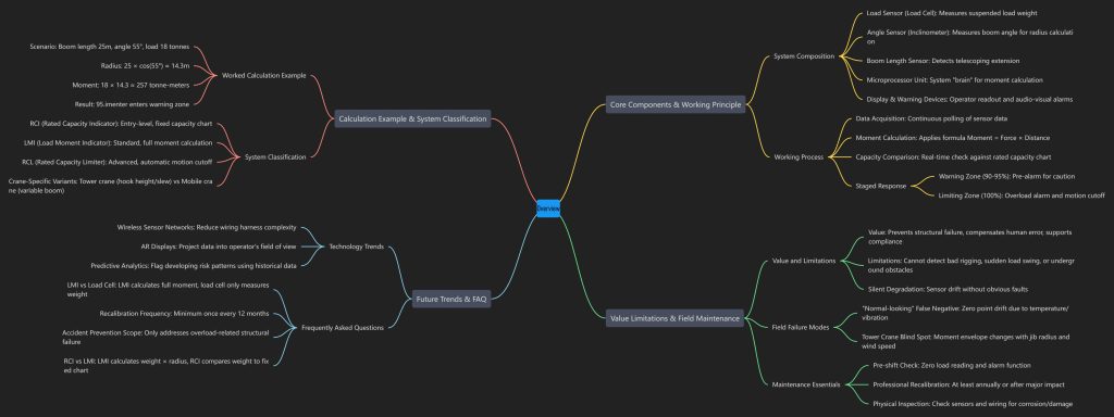
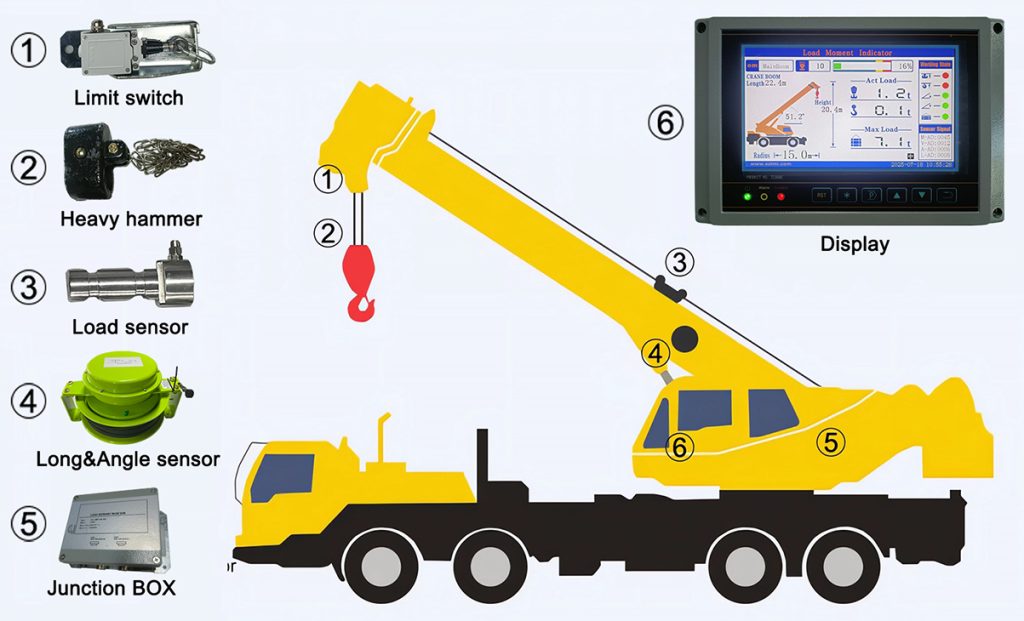
An LMI is not a single device — it’s a coordinated network of sensors and processing hardware that together give the crane something like situational awareness.

组件功能:Typical LocationHow It Works
Load sensor (load cell)Measures actual suspended load weightHoist rope dead end, or boom baseStrain gauge or pressure transducer detects deformation under load
Angle sensor (inclinometer)Measures boom angle relative to horizontal — a key input for radius calculationMounted on the boom bodyPotentiometer or Inertial Measurement Unit (IMU)
Boom length sensorDetects telescoping boom extension to determine working radiusAlong telescoping boom sectionsString potentiometer, rotary encoder, or ultrasonic sensor
Microprocessor unitThe system’s “brain” — ingests all sensor data and runs the moment calculationCentral control cabinetCompares real-time moment against the stored rated capacity chart
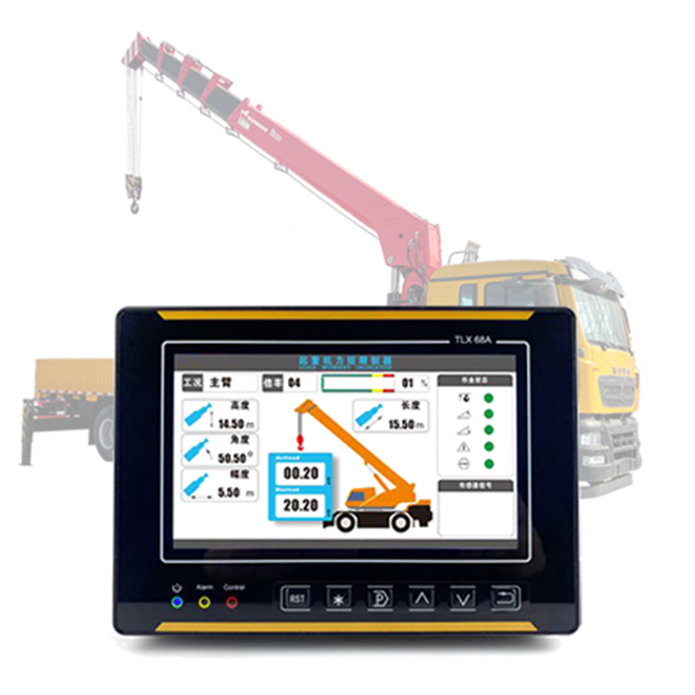
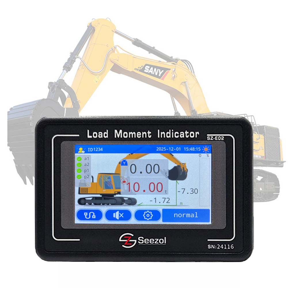
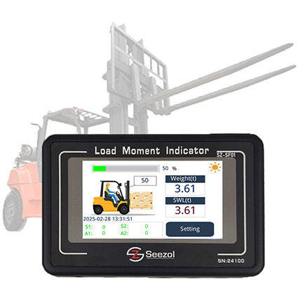
Display unitOperator-facing readoutCab-mounted panelShows load weight, % of rated capacity, boom angle, and radius in real time
Warning devicesAlerts and cutoffCab and/or boom-mountedAudio-visual alarms plus, on most modern systems, automatic motion cutoff

2. Working Principle: From Data to Decision

The LMI runs as a high-frequency closed-loop control system, typically re-evaluating several times per second so there’s effectively no lag between a changing lift condition and a safety response.
1. Data acquisition — the system continuously polls the load, angle, and length sensors, and on many systems also tracks outrigger position and, on larger units, wind speed.
2. Moment calculation — the processor applies the basic physics relationship Moment = Force × Distance to compute the current load moment.
3. Capacity comparison — that real-time moment is checked against the crane’s rated capacity chart for the current boom length, angle, and outrigger configuration.
4. Staged safety response:

  • Warning zone (typically 90–95% of rated capacity): pre-alarm, prompting the operator to proceed with caution.
  • Limiting zone (100% of rated capacity): overload alarm activates, and on most modern systems the crane automatically restricts motion in the direction that would worsen the overload (e.g., hoisting up or booming out).

5. Continuous monitoring — this cycle repeats uninterrupted for the duration of the lift.

3. Worked Example: How the Math Actually Works

Numbers make this concrete. Suppose a telescopic crane is configured as follows:

  • Boom length: 25 m
  • Boom angle: 55° from horizontal
  • Working radius = boom length × cos(boom angle) = 25 × cos(55°) ≈ 25 × 0.574 ≈ 14.3 m
  • Actual load on the hook: 18 tonnes
  • Load moment = load weight × radius = 18 × 14.3 ≈ 257 tonne-meters
  • Rated capacity at 14.3 m radius (from the load chart): 270 tonne-meters
  • Capacity utilization = 257 / 270 ≈ 95.2% → the LMI enters its warning zone and alerts the operator before any further boom-out or hoist-up movement would push the lift over 100%.

This is the calculation happening several times a second, invisibly, throughout the lift — which is exactly why manual load-chart reading under time pressure is so much more error-prone than an automated system running the same formula continuously.

4. System Classification: RCI, LMI, RCL, and Crane-Specific Variants

系统类型Full NameFunctional Characteristics
RCIRated Capacity IndicatorEntry-level; monitors load weight against a fixed capacity chart without full moment calculation
力矩限制器负载力矩指示器Standard configuration; calculates full moment, provides staged audio-visual alarms, prevents structural overload
RCLRated Capacity LimiterAdvanced version; alarms  automatically cuts off the motion circuits that would cause an overload
塔式起重机 LMI-Adds hook-height and slew-angle monitoring specific to tower crane geometry
Mobile Crane LMI-Adapts to the variable boom configurations of hydraulic telescopic cranes

The practical distinction that trips people up most often: an RCI tells you what the load weighs relative to a chart, while a true LMI tells you whether your entire current configuration — weight, angle, radius — is within the safe envelope. Only the latter accounts for the fact that the same weight can be safe at a short radius and dangerous at a long one.

5. Value and Limitations — an Honest Assessment

What an LMI genuinely does well:

  • Prevents structural failure — catches the overload conditions that cause boom buckling or crane tip-over before they happen.
  • Compensates for human error — acts as an objective second check against operator misjudgment of radius or weight, particularly under time pressure or poor visibility.
  • Supports regulatory compliance — in the United States, OSHA’s construction crane standard (29 CFR 1926.1417(o)(3)(ii)) requires load-monitoring devices on most crane configurations, naming load moment indicators specifically as an acceptable compliance method; comparable requirements exist under ASME B30.5, the EN 13001 series in Europe, and GB/T 12602 in China.
  • Provides data traceability — modern systems log lift data in a “black box” style record, useful for both incident investigation and routine process review.

What it does not do, and this is worth being blunt about:

  • It cannot detect bad rigging. Incorrect sling angles, damaged hardware, or a poorly balanced load can all be present while the LMI reads a perfectly “safe” condition — it monitors the crane’s configuration, not the rigging.
  • It cannot anticipate sudden load swing or underground obstacles. Those are separate hazard categories entirely.
  • It degrades silently if uncalibrated. A drifting sensor doesn’t necessarily throw an obvious fault; it can simply read slightly wrong, which is more dangerous than an obvious failure because nothing on the display looks abnormal.
  • Environmental extremes affect accuracy. Vibration, temperature swings, and electromagnetic interference from nearby equipment can all shift sensor readings — which is why ingress protection rating (IP65 minimum for outdoor use) and EMC compliance matter as much as the headline accuracy spec when selecting a system.

A peer-reviewed engineering review of crane rollover prevention (indexed on PMC/NCBI) reports that U.S. federal investigators recorded 502 crane-related construction deaths across 479 incidents over the 1984–1994 period — a statistic frequently cited in the case for automatic moment limiting as a regulatory baseline rather than an optional add-on. It’s worth noting, in fairness, that the same literature is clear that overload is one contributing factor among several (rigging failure, ground instability, and power-line contact are others), which is exactly why “we have an LMI” isn’t the same as “we have a fully safe lift.”

6. Field Notes: What Actually Goes Wrong in Practice

Note 1 — the “normal-looking” false negative. A common pattern we’ve seen on mobile crane retrofits: the LMI passes its annual inspection with a correctly calibrated load cell, then over the following months the zero point drifts a few percent due to temperature cycling and vibration. The display still looks completely normal, and the alarm threshold hasn’t moved — but the actual trip point has shifted just enough that a borderline lift that should trigger a warning doesn’t. Nothing about the system looks broken. That’s what makes it dangerous.
Note 2 — the tower crane blind spot. On tower cranes, hook height and slew angle interact with wind loading in ways that a mobile-crane-style LMI configuration doesn’t fully capture. Crews used to mobile crane LMIs sometimes carry over the same “the display is green, we’re fine” habit to tower crane work, without accounting for the fact that a tower crane’s moment envelope changes with jib radius and wind speed simultaneously — two variables mobile crane operators don’t usually have to track together.
The common thread in both notes: the failure isn’t the sensor, it’s the assumption that a quiet display means an accurate one.

7. Maintenance Essentials

  • Before every shift: confirm the display reads correctly at zero load and that audio-visual alarms function.
  • At least once every 12 months, or after any major impact: full professional recalibration against a certified test load — not just a visual inspection.
  • After extended storage (6+ months) or any sensor replacement: recalibrate before returning the crane to service.
  • Ongoing: physically inspect sensors and wiring for corrosion, loose connections, or mechanical damage — a perfectly calibrated sensor with a corroded connector will still produce bad data.

8. Where the Technology Is Headed

Several trends are visible in current-generation LMI development, though it’s worth applying a healthy amount of skepticism to vendor roadmaps versus what’s actually deployed at scale:

  • Wireless sensor networks — reducing the wiring harness complexity that causes a meaningful share of field failures today.
  • Augmented reality (AR) displays — projecting key load data into the operator’s field of view rather than requiring a glance at a separate panel; currently more common in pilot programs than standard equipment.
  • Predictive analytics and machine learning — using historical lift data to flag developing risk patterns (such as gradual sensor drift) before they become active faults, and, on multi-crane sites, feeding into anti-collision coordination systems.

None of these directions change the underlying physics — they change how quickly and clearly the same moment calculation reaches the operator, and how early a maintenance issue gets caught.

9. FAQ

Is an LMI the same as a load cell?
No. A load cell is one component (weight measurement) inside a complete LMI system. An LMI combines load weight, boom angle, and boom length data to calculate the full load moment — a load cell alone only tells you the weight, not whether the current configuration is safe.

How often should an LMI be recalibrated?
At minimum once every 12 months, and additionally after any major impact, sensor replacement, or extended storage of six months or more.

Can an LMI prevent all crane accidents?
No. It specifically addresses overload-related structural failure and tipping. It does not detect improper rigging, sudden load swing, ground instability, or power-line contact — all of which require separate controls and operator training.

What’s the difference between an RCI and a full LMI?
An RCI compares load weight to a fixed capacity chart without calculating the full moment. An LMI calculates load weight × working radius continuously, which is necessary because the same weight can be safe at a short radius and dangerous at a longer one.

Do tower cranes need a different type of LMI than mobile cranes?
Yes — tower crane systems need to account for hook height, slew angle, and jib radius in combination with wind loading, which differs meaningfully from the boom-angle-and-length calculation used on mobile telescopic cranes.

10. About This Article

Editorial standards: Technical claims here are checked against publicly available regulatory text (OSHA, ASME, EN, GB/T) and peer-reviewed engineering literature at the time of writing. Where a number is presented as an industry baseline rather than one vendor’s marketing claim, we’ve tried to say so explicitly.
Corrections: This is treated as a living document. If you spot an inaccuracy — particularly around a specific regulatory clause — flag it, and we’ll correct and re-date the article rather than silently editing it.
Contact: For corrections or questions, reach the editorial desk at safety-editorial@[yourcompany-domain].com (replace with your real contact before publishing).

Sources Referenced

  • OSHA 29 CFR 1926 — Cranes and Derricks in Construction, operational aids provisions (via up.codes regulatory text database)
  • Kim et al., “Economical Auto Moment Limiter for Preventing Mobile Cargo Crane Overload,” peer-reviewed engineering literature (PMC/NCBI), citing U.S. federal crane incident data for 1984–1994
  • ASME B30.5 (Mobile and Locomotive Cranes) — general reference for load moment indicator requirements
  • EN 13001 series (EU) and GB/T 12602 (China) — regional crane load-monitoring standards; consult your regional standards body for authoritative full text

新产品

联系客服

请填写下表,我们将尽快与您联系。