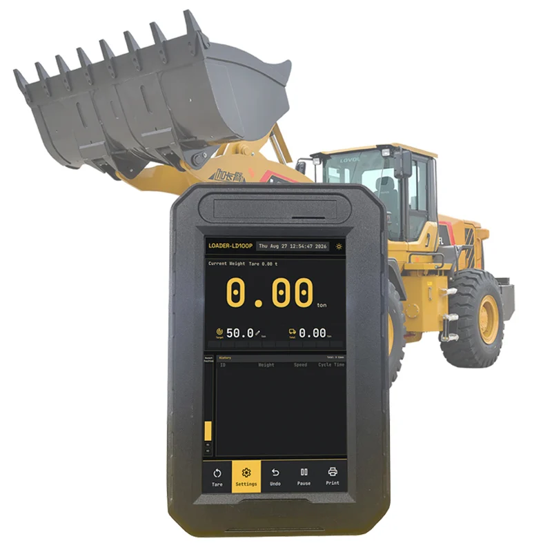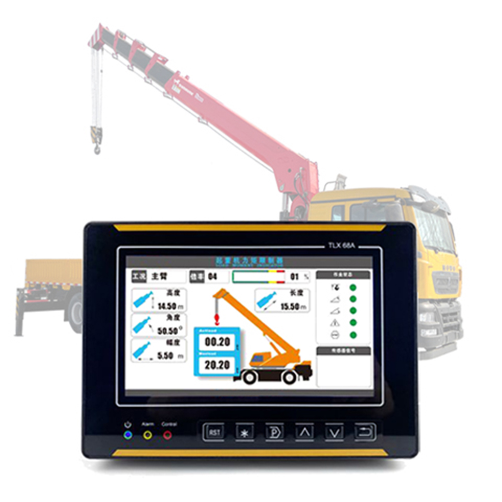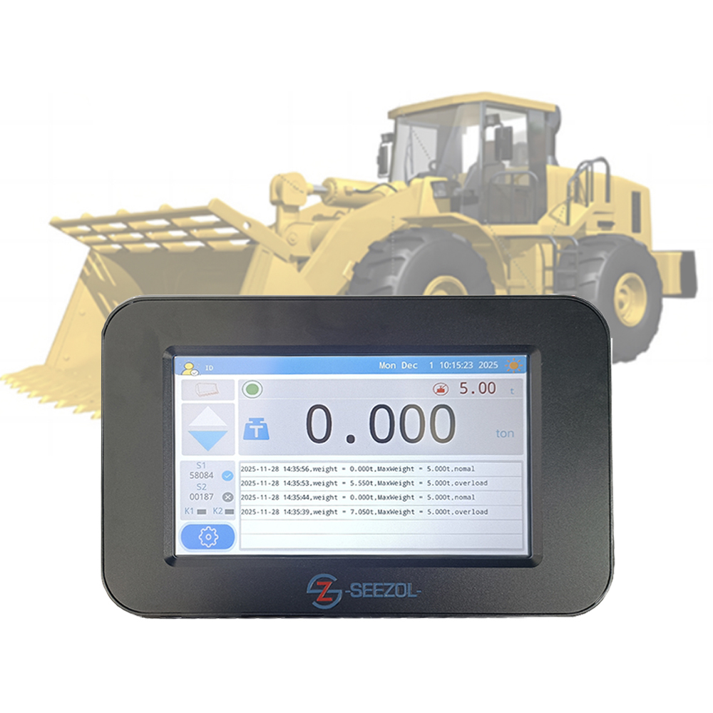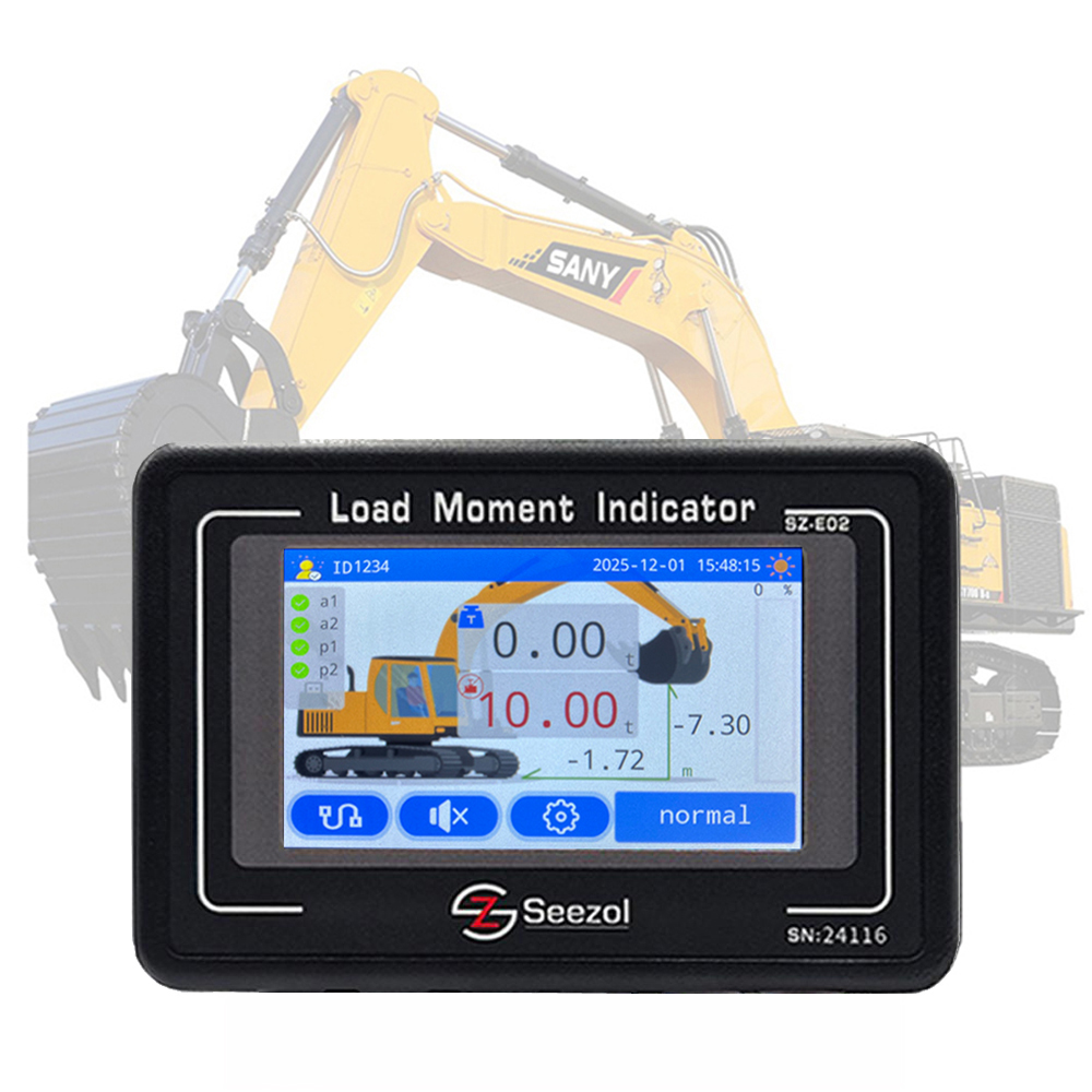
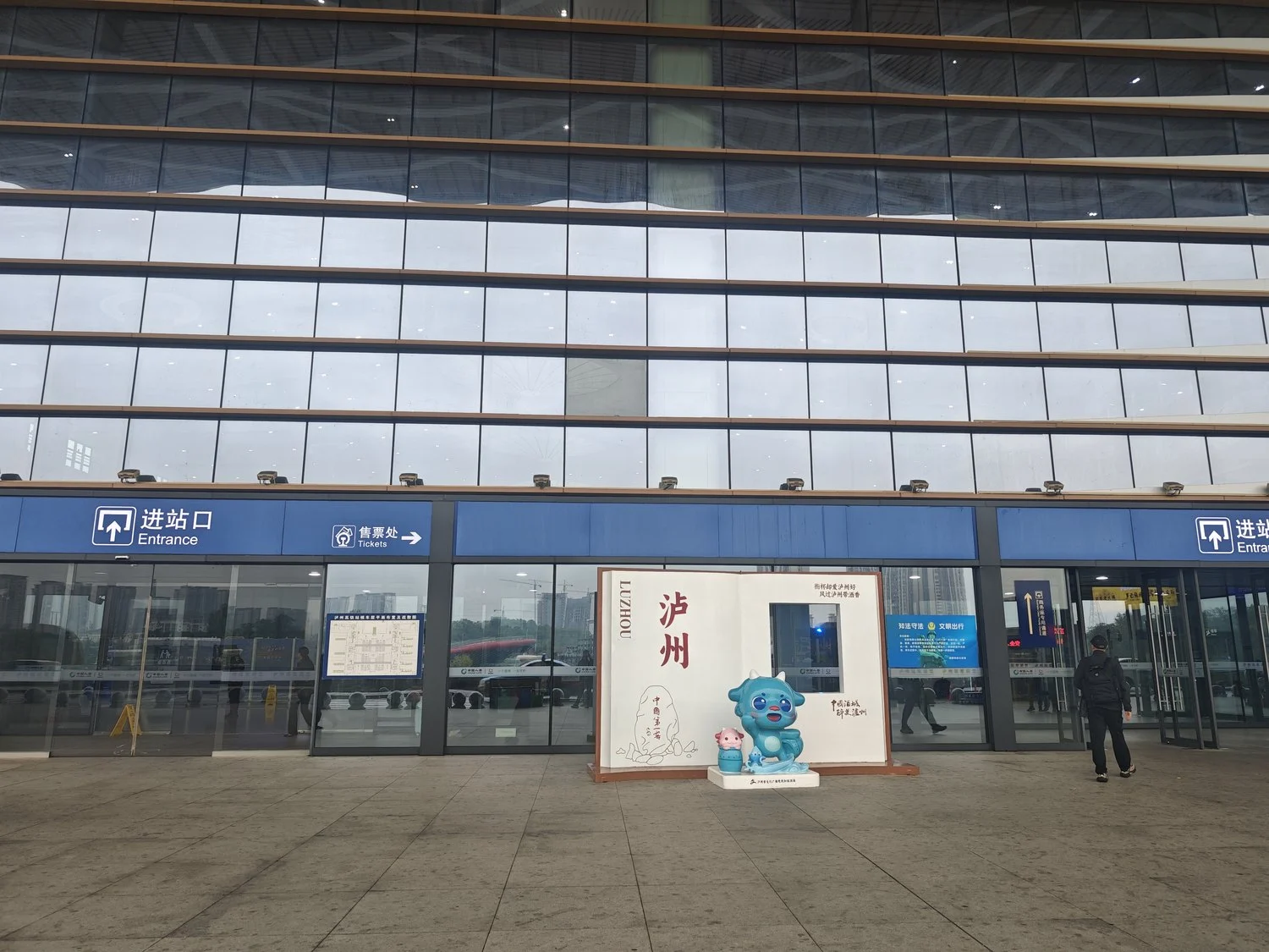
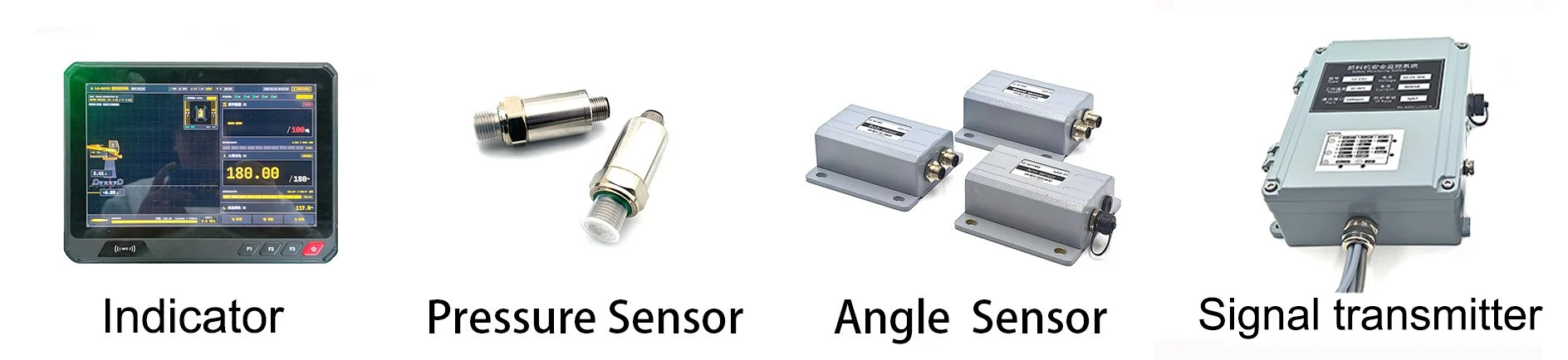
On 26–28 October 2026 two SeeZol engineers were at Sichuan Bangli Heavy Machinery’s works in Luzhou, Sichuan, fitting a load moment indicator to a 140-ton crawler-mounted material handler with a shell grab. The superstructure sits on a raised gantry, which puts the boom pivot 10 m above ground; the machine reaches 25 m. Almost every mounting point had to be reached from a boom lift, and nothing could be positioned by eye. Five sensors went on — body attitude, boom angle, stick angle, and two pressure channels on the boom cylinder — feeding an SZ-E01 acquisition unit that talks over CANopen to the new LMI-8000 Linux terminal. What follows is the survey, the mounting points, the harness, the calibration, and the three details we think decide whether the readings still hold next October.
1. Where it happened, and what the machine is
Bangli — Sichuan Bangli Heavy Machinery Co., Ltd., in the high-tech industrial park at Luzhou on the Yangtze — traces its line back to the Changjiang Excavator Works. The company licence-built the Liebherr R961 in 1977 and took the full R962 / R972 / R982 package in 1985, and it now runs a 400,000 m² plant with roughly 500 staff, building 6.5–220 t hydraulic excavators and 10–200 t material handlers. ISO 9001, ISO 14001 and ISO 45001 are in place, and the technical centre is provincial-level.
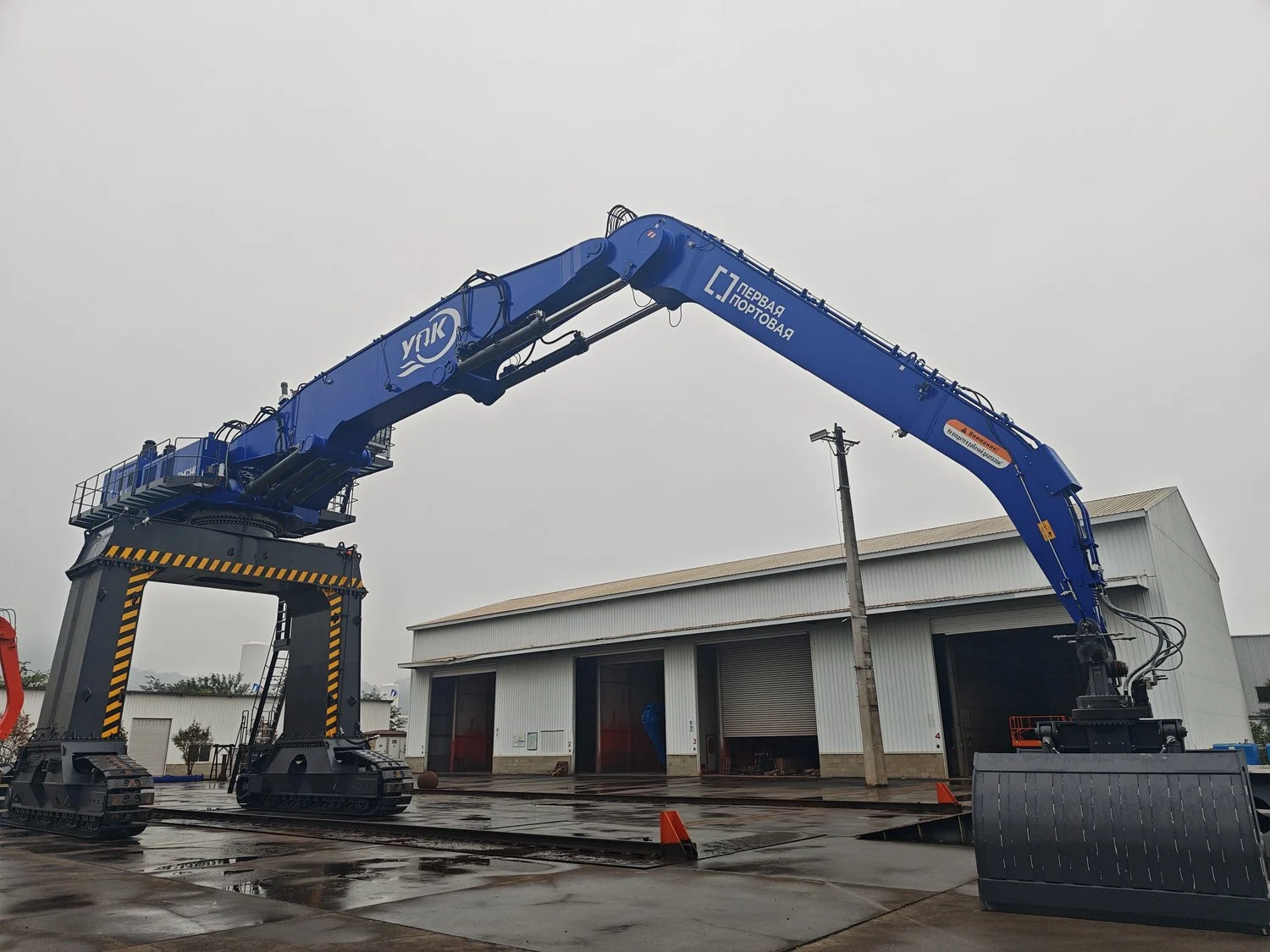
The machine in the yard is a 140-ton shell-grab handler on a raised crawler gantry. Two crawler tracks, a fabricated portal frame, and the superstructure carried high on that frame — raised to suit the working environment on site, which is what puts the boom pivot 10 m above ground. Gooseneck boom, hydraulic shell grab, and the cab sitting low on the superstructure so the operator looks along the boom instead of down at it. The boom carries the end customer’s livery: the YNK mark and Russian lettering.
Two numbers set the whole job. The boom-to-body hinge is 10 m above ground — not because the boom is that long, but because the body sits on a riser — and the machine reaches 25 m at full extension. The load chart is written from ground level, so both numbers enter the radius and height conversion directly; and both put the sensor pads well above where a ladder ends. Nothing on a load moment indicator job at this height is a one-man operation.
2. Why a 25 m material handler is harder on a load moment indicator than a mobile crane
A truck crane is a well-behaved machine to instrument: one hinge, one telescopic boom, a rope with a known multiplier, and a load cell in the dead end. A shell-grab handler gives you none of that.
Radius is not a function of one angle. The boom is a gooseneck with an extra knuckle, and the stick swings on its own hinge. Where the grab actually hangs depends on boom angle, stick angle and grab position together. One degree of boom angle at 25 m is 25 × π / 180 ≈ 0.44 m of radius — and 0.44 m at a rated 10.9 t is roughly 4.8 t·m of moment. Resolve this with two angles and long-reach readings drift by metres.
The machine is never level. A crawler gantry stands on whatever the yard floor happens to be — paving, crushed stone, the compacted edge of a stockpile — and the two tracks never carry the same load. One to two degrees of roll is ordinary, and it changes as the machine walks and as the ground under it takes weight. The riser makes that worse rather than better: with the pivot 10 m up, one degree of roll displaces it 0.17 m sideways and about the same in height, and both numbers go straight into the radius and height conversion. A system that assumes level carries that error through every reading of the shift. Hence the body attitude sensor: measure roll and pitch and correct, rather than assume.
There is no rope. Load has to come from cylinder pressure, which means two chambers, seal friction, and a circuit full of valves. Pressure is not a proxy for load until it is calibrated against radius, and it moves with oil temperature, which is why this kind of load moment indicator needs more than a single calibration point across the working range.
The system is designed against ISO 10245-1 for limiting and indicating devices, GB/T 12602 for overload protection on lifting appliances, and EN 13000 where the machine is exported. Those standards say what the device must do — warn, and where required, stop. They do not make the numbers right. The survey and the calibration do that — which is why a load moment indicator takes a day of measuring before anyone opens a configuration screen.
3. What we fitted: a Linux load moment indicator terminal and its sensing chain
The load moment indicator on this machine runs the current generation, and the change is bigger than a new screen. The previous generation was a microcontroller board with fixed firmware: the display showed moment and angle, the parameter set was flashed at the factory, and any change meant a new firmware build. The LMI-8000 terminal in this cab is a Linux machine. Calibration is a screen you walk through with the operator, language and units are settings rather than builds, and the logs are files that can be copied out of the cab.
The split between the two boxes is deliberate. Safety judgement — overload thresholds, relay drive, the decision to inhibit a motion — stays in the SZ-E01 acquisition unit, which is a deterministic real-time controller on CANopen. The Linux terminal does display, logging and human interface. Linux buys a usable UI, storage and a network stack; it does not buy a bounded response time after a cold boot. Keeping the trip in the acquisition unit means the terminal can be rebooted, swapped or updated without the machine losing overload protection for a single cycle.
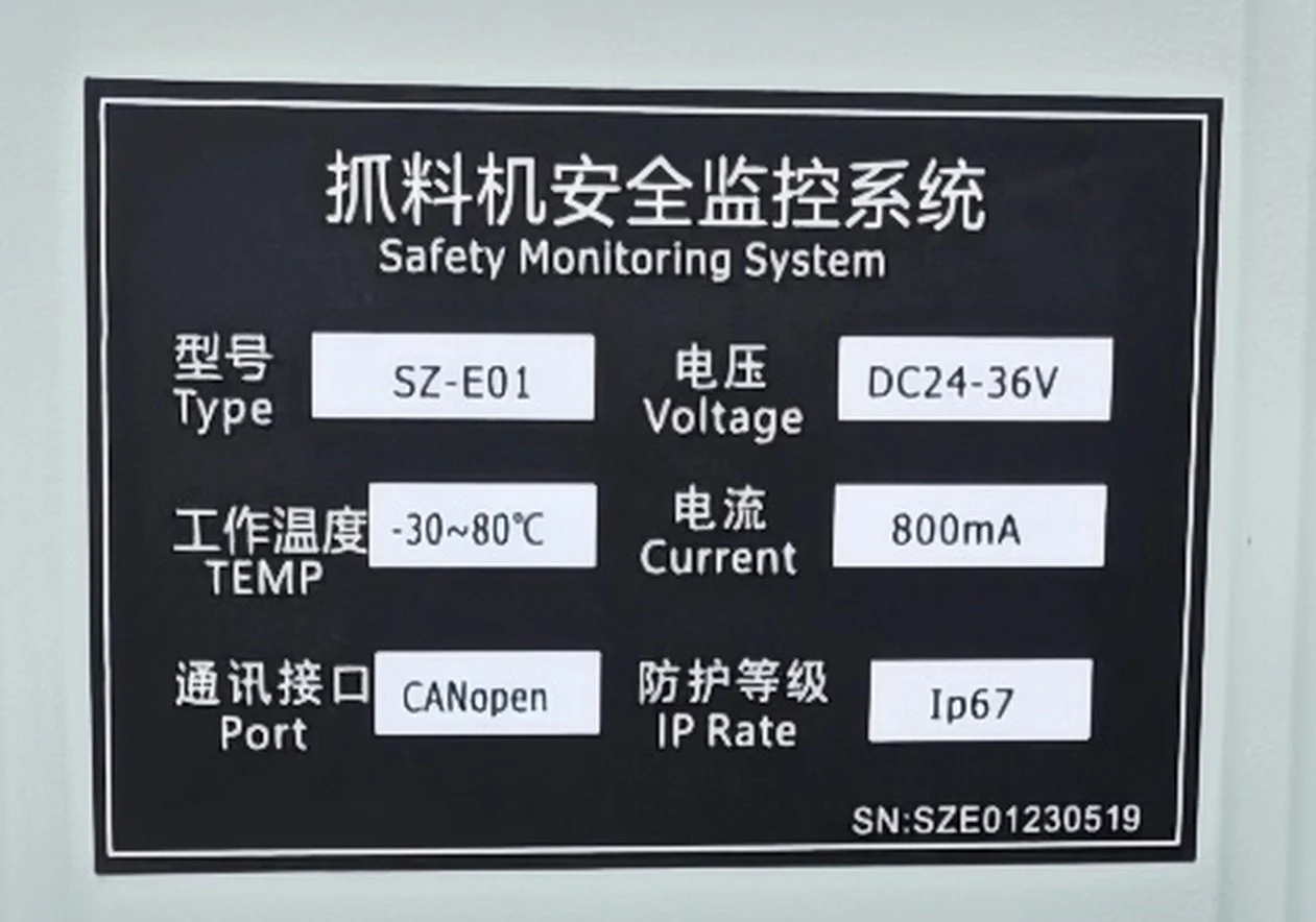
The nameplate on the unit, photographed on the machine, is the part worth quoting, because it is the only specification on this page that came off the metal rather than off a datasheet.
| Artigo | Valor | Source |
|---|---|---|
| Acquisition / control unit | SZ-E01 | Nameplate |
| Terminal de visualização | LMI-8000, Linux platform | Terminal screen |
| Tensão de alimentação | DC 24–36 V | Nameplate |
| Current draw | 800 mA | Nameplate |
| Temperatura de funcionamento | −30 °C to +80 °C | Nameplate |
| Fieldbus | CANopen on the unit; CAN link to the terminal, synchronised | Nameplate + screen status bar |
| Proteção contra a penetração | Ip67 | Nameplate |
| Unit serial number | SZE01230519 | Nameplate |
| Nominal system error | ±3 % | SeeZol product data |
| Channel | Modelo | Range / accuracy | Mounting point |
|---|---|---|---|
| Body attitude | SZ-A01BD | ±10–90°, 0.1° absolute, 0.05° resolution, IP67 | Slewing platform, machined pad, axes aligned to machine datum |
| Ângulo da lança | SZ-A01BM | Same family, 9–36 VDC, 0.02 s response | Boom web above the root hinge, machined pad |
| Stick angle | SZ-A01AM | Same family | Stick root hinge |
| Boom cylinder, piston side (P1) | SZ-P201S-400 | 0–400 bar, 4–20 mA, 0.5 % F.S., 0.1 bar | Adaptor block at the cylinder head end |
| Boom cylinder, rod side (P2) | SZ-P201S-400 | 0–400 bar, 4–20 mA, 0.5 % F.S., 0.1 bar | Valve block test port, boom cylinder circuit |
Two error figures on this load moment indicator have to be kept apart. The transmitter is 0.5 % F.S., which on a 400 bar range is 2 bar. The system figure is ±3 %, which at a rated 10.9 t is ±0.33 t. The first describes one channel’s linearity; the second includes geometry, calibration and hydraulic friction. Quote the second to a customer, never the first — and never let a tender document mix them.
4. How a material handler load moment indicator gets installed, sensor by sensor
Five channels make up this material handler load moment indicator, and each one answers a different question: where the platform is, where the boom is, where the stick is, and how hard the cylinder is pushing from each side. Get any one of them wrong and the others cannot compensate.
4.1 Angle channels: body, boom, stick
Three angle sensors on this load moment indicator, all from the SZ-A01 family: 9–36 VDC, 0.1° absolute accuracy, 0.05° resolution, 0.02 s response, IP67. Each one is a gravity reference, so each one has to be mounted to a surface whose relationship with the machine’s geometry is known and stable.
Body (SZ-A01BD). A machined pad on the slewing platform, aligned to the machine’s longitudinal and transverse axes. This channel exists to serve the second problem in section 2: it measures how far the gantry is off level, and the controller uses that to correct radius and height. On a crawler machine that walks onto unprepared ground and gets packed up under the tracks before a lift, it is not a nicety.
Boom (SZ-A01BM). On the boom web, a short distance above the root hinge, on a pad machined after the boom was welded. This one is a gravity reference, so what it needs is not a mechanism but a surface whose angle to the boom centreline is known and does not change. A welded boom web is not that surface: across the footprint of the sensor it is out of flat by more than the 0.1° the sensor is specified to. So the pad is machined, the sensor is bolted down to it, and the cable leaves downward into a drip loop before it is clipped along the web at the same pitch as the hose clamps.
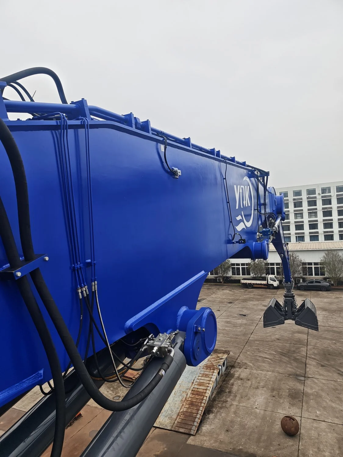
Stick (SZ-A01AM). Same arrangement at the stick root. This is the channel a two-angle crane load moment indicator does not have, and on this machine it is not optional: with a gooseneck boom and a stick that swings on its own hinge, boom angle alone cannot tell the controller where the grab is.
4.2 Pressure channels P1 and P2
The pressure side of a hydraulic load moment indicator is where its accuracy is actually won or lost. Two SZ-P201S transmitters, 0–400 bar, 4–20 mA, on the boom cylinder circuit: P1 on the piston side, P2 on the rod side. Neither is taken by cutting a hose. P1 comes off a machined adaptor block bolted at the cylinder head end, which puts the transmitter on a flat face at the piston-side gallery and keeps it clear of the hose bundle; P2 comes off a test port on the valve block, where the rod-side gallery is already brought out. Fewer joints in a 35 MPa circuit, and both points isolate for service without draining anything.
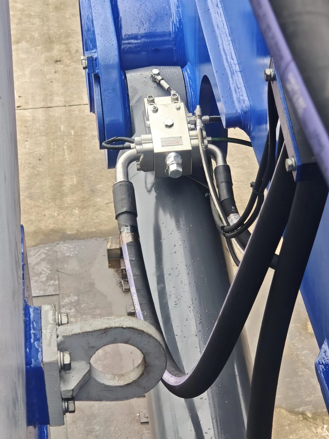
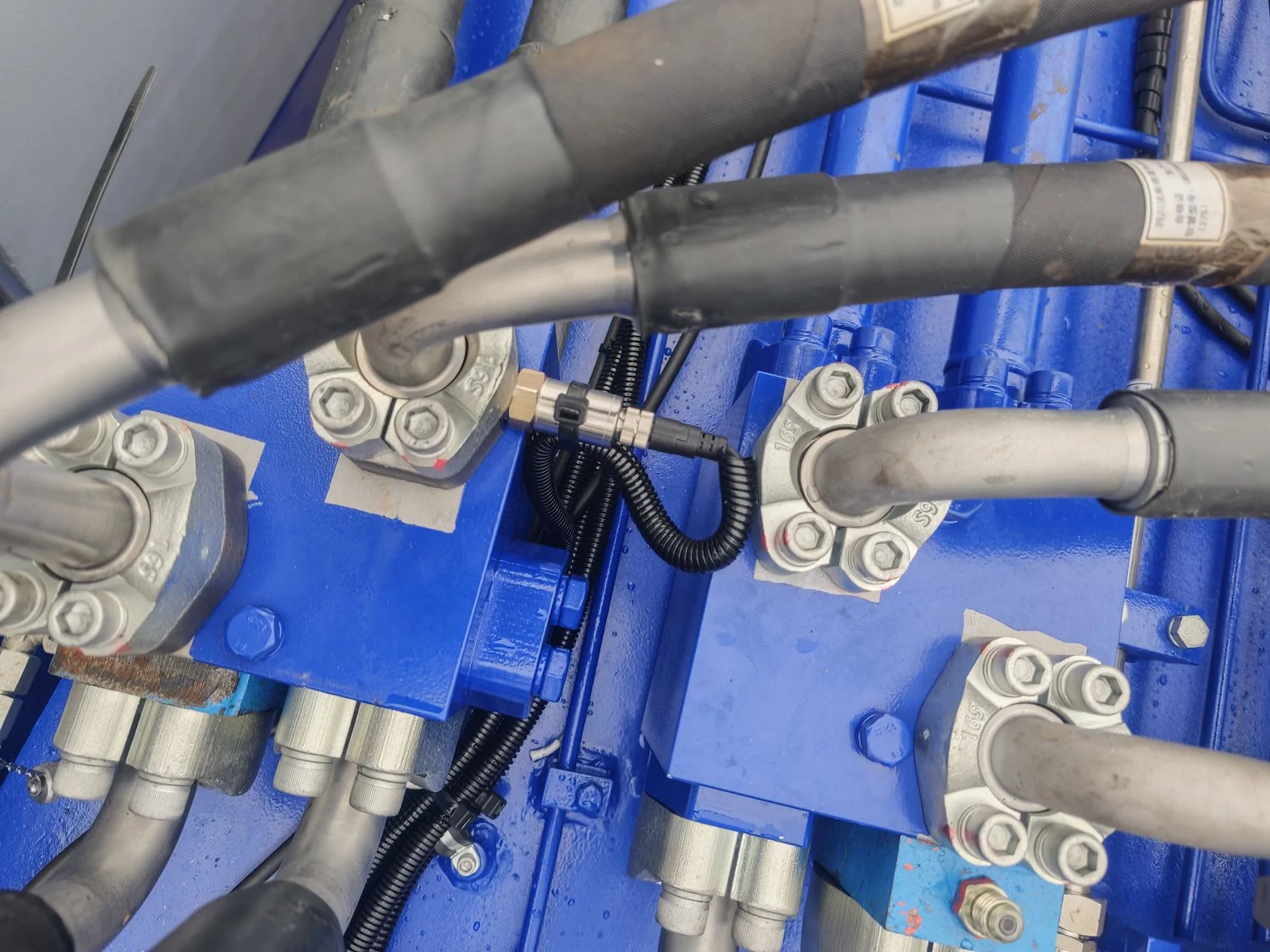
Two channels rather than one, because the boom cylinder is differential. Piston-side pressure alone gives force in one direction only; with the rod-side channel the controller can subtract the annulus area and the return-line back pressure. A grab machine spends half its cycle holding a load at reach and half swinging empty, and without that subtraction the empty swing reads as a few hundred kilos of load that is not there.
Practical note: P2 sits at low pressure most of the time, so it is the channel that suffers first when there is air in the line. Bleed both, then zero. A bubble in the rod-side line shows up as a zero that drifts for the first hour of every shift, and operators learn to distrust the display long before anyone thinks to bleed it.
4.3 Acquisition unit and junction boxes
The SZ-E01 — the box that does the arithmetic behind the load moment indicator — sits in a die-cast enclosure on the superstructure side wall, high up under the handrail, away from the spray path of the return filter. Below it is the machine’s own cable box, and to one side the two red valve blocks of the boom circuit.
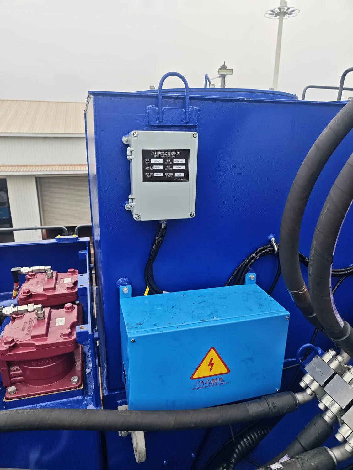
Mounting rules we do not bend at this height: glands facing down, enclosure on standoffs so water runs behind it instead of pooling at the gasket, stainless fasteners with threadlocker, and cable entry on the underside even when the top is easier to reach from the lift.
4.4 Harness: ten metres up, and it has to survive the swing
Both the sensors and the display are on the rotating half of the machine, so the run never crosses the rotary joint — a real advantage over a portal crane with the cab on the fixed side. The hard part is the boom root: two hinges’ worth of relative motion inside half a metre, next to a bundle of hoses that flex every cycle.
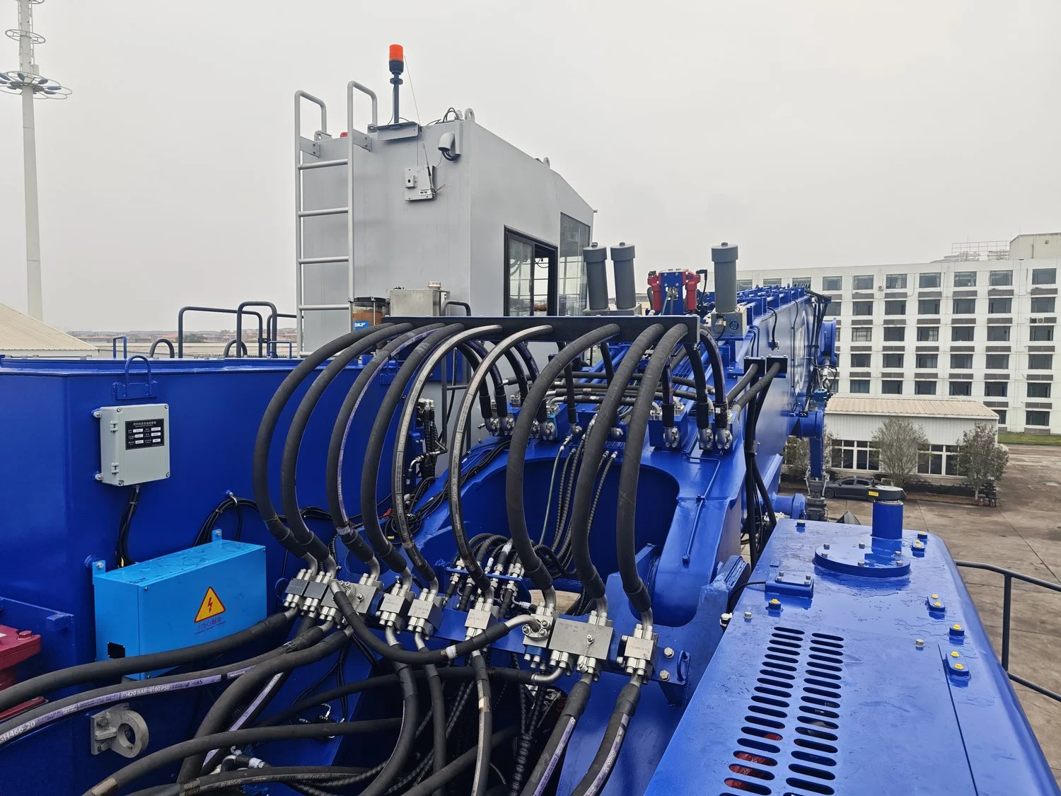
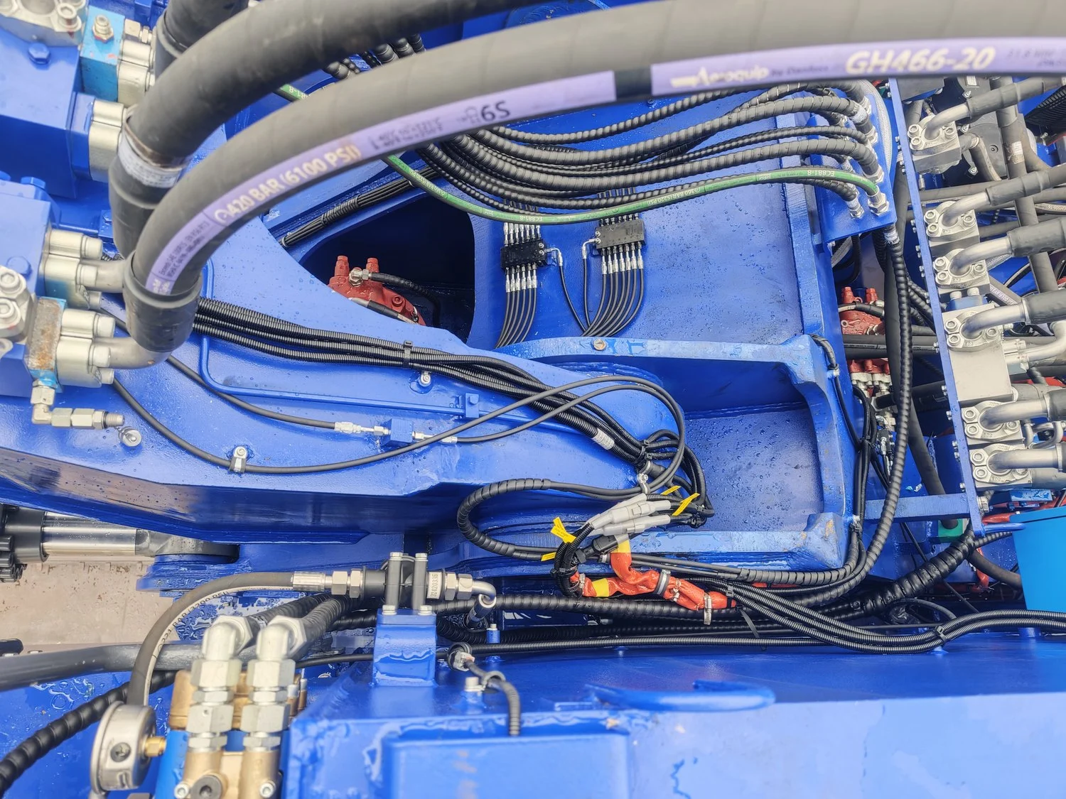
Split corrugated conduit on the existing clamps, a service loop at each hinge, a drip loop before every gland, and Deutsch-style connectors at the boom root. That last item is not about reliability. It is about the day the machine goes on a lowbed: the boom comes off, and nobody should be cutting a sensor cable to make that happen.
4.5 The display in the cab
The load moment indicator terminal, an LMI-8000, sits on the right-hand post, in the operator’s sight line when the grab is at reach. The F1–F3 keys under the screen are physical, which is the right call: this operator wears gloves all day, and a capacitive panel through a work glove is a bad interface.
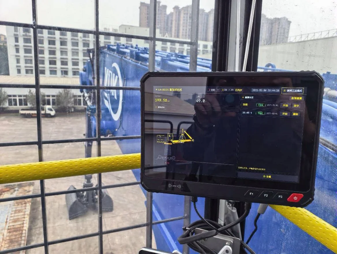
What the screen was showing at that moment: the CAN link synchronised with the acquisition unit, boom at 49.8°, and the calibration page with two records — empty and 18.00 t — both flagged as calibrated. Night mode is a single button on the status bar; it drops the panel to a dark palette and dims the backlight, which matters on a night shift with the cab lights off and a glare-free windscreen.
The network field is empty on this machine. The terminal supports it; the yard did not ask for remote access, and we do not switch on a network stack that nobody is going to administer. If they want log uploads later, the terminal already has the interface — that is a cab job, not a machine job.
5. Calibration: geometry first, then two points
Installation is the easy half of a load moment indicator job. On a machine this size the geometry is where the error hides, so before anyone touched the calibration page we measured.
Check 1 — radius. Tape from the slew centre to the grab pin at three boom angles, compared against the geometry model. This is the check that catches a sensor bracket fitted against the wrong datum face, before it turns into a calibration offset nobody can explain three months later.
Check 2 — zero. Grab empty, machine levelled on packers under the tracks, boom at mid-range, both pressure channels bled and then zeroed. Zeroing with the grab resting on the ground is the classic mistake: you zero in the weight of the grab that the ground is carrying, and the machine carries a constant offset for the rest of its life.
Check 3 — loaded point. One known load of 18.00 t, taken at three radii. That is the second calibration record on the screen in Fig. 12. Two points — empty and one known load — fix the gain. The third radius is what tells you whether the stick channel is doing its job or just adding noise.
Then the part that does not appear in any acceptance document: half an hour with the operator. What the alarm means, what a bypass does and does not allow, and how to tell a real overload from a sensor fault. On a grab machine the operator is the only person who looks at this display all day. If he does not trust it, he will ignore it — and an ignored load moment indicator is worse than no indicator, because it puts a number on a decision that used to be made with judgement.
6. Field notes: three things that decide whether this load moment indicator still reads true next October
1. Water follows cable, not gravity. It rained for two of the three days. Every photograph in this report has water on the paint. The three failures that follow rain on a machine like this are a gland facing up, a drip loop that is actually a U-trap, and a connector boot that was pushed on but not locked. All three are invisible at commissioning and all three show up as an intermittent angle channel six months later.
2. Air in the rod-side line. P2 is the channel that gets forgotten, because it reads near zero most of the day and nobody notices it drifting. Bleed it at commissioning, bleed it again after the first week of work, and note in the handover that a zero which walks is air before it is a failed sensor.
3. The clock and the calibration file. The screen in Fig. 12 reads 2021-09-06 22:44:36 — the factory default real-time clock, not the day of the job — and both calibration records carry that same date. It is harmless on the day. A year later, when someone is trying to work out which sensor was replaced and when, a file in which every event happened on the same September evening is worth nothing. Set the clock at commissioning, export the calibration file, and file it with the machine’s records. On a Linux terminal that export is a USB stick and thirty seconds; on the old fixed-firmware display it was a service laptop and a phone call.
7. What the customer actually received
The delivered material handler load moment indicator consists of three angle sensors (body, boom, stick), two pressure transmitters, one SZ-E01 acquisition unit, one LMI-8000 terminal, the harness with hinge service loops and Deutsch connectors at the boom root, mounting brackets, the drawing set (mounting positions and wiring), the calibration record, a spare connector and gland kit, and half an hour of operator briefing.
Three relay outputs, K1–K3, are available on the acquisition unit of this load moment indicator for motion cut-off, and the harness for it is part of the standard build. Whether to enable cut-off on a grab machine is the customer’s call, not ours: some yards want the boom to slow at the threshold, others want it to stop, and a few want alarm only during the first months of operation while operators get used to the display. What the system must not do is decide that on the customer’s behalf.
What a load moment indicator means in the yard, in plain terms: the operator gets a load and radius reading before the grab leaves the pile instead of after the machine feels light on one side; the yard gets a per-cycle log it can reconcile against inbound and outbound tonnage; and a machine going out to a new site carries its calibration record with it instead of a technician’s memory.
8. FAQ: load moment indicator questions from this job
Can we invoice off this load moment indicator instead of a weighbridge? No. It is a safety device with a ±3 % system figure; on a 10.9 t rated load that is ±0.33 t. A trade weighbridge is an order of magnitude tighter and legally verified. Use this to prevent overloads and to log trends, and invoice on a certified scale.
Why three angle sensors when cranes use two? Because the boom is a gooseneck and the stick swings on its own hinge. Two angles cannot resolve where the grab is at 25 m. The third channel is what makes the radius reading a measurement rather than an estimate.
Does moving the display to Linux weaken the safety function? Not if the safety logic stays in the real-time acquisition unit, which is how this load moment indicator is built. The terminal displays, logs and takes input. The trip decision is made in the SZ-E01 and driven out through its relays.
How long does installation take on a machine this size? Two working days is the typical figure for the mechanical and electrical work, plus calibration; on this machine the high-reach mounting set the schedule, not the wiring. Machines with the cab on the fixed side and a slip ring in the path take longer.
Can we keep an older machine and only change the display? Usually yes, if the acquisition unit’s CANopen protocol matches the terminal’s. But recalibrate anyway. A new terminal running an old calibration file is the most common way to end up with a number that looks right and is not.
9. Tell us the machine, we will come back with a configuration
For a quotation that is not guesswork we need six numbers: rated capacity, boom pivot height, maximum reach, boom and stick cylinder bore and rod diameter, relief pressure, and whether the machine is for protection only or also for internal weighing. With those, a configuration and a mounting sketch come back within one working day.
About this report. Written by the SeeZol field engineering team from site records and photographs taken at the Sichuan Bangli Heavy Machinery works, Luzhou, 26–28 October 2026. System design of this load moment indicator references ISO 10245-1, GB/T 12602 and EN 13000. All figures in Table 1 were read off the unit nameplate or the terminal screen on site; component data in Table 2 comes from SeeZol product documentation.
Leituras relacionadas: the 300-ton port grab installation at Huanghai Machinery · how to choose a load moment indicator in five steps · oil pressure sensor installation guide · material handler load indicator product page · LMI selection by machine type